Dan Sarandrea (Phila)
Waitin' On Parts...
The Leiszig windshield wiper mod was the first mod I saw after joining XWeb about four years ago, and I immediately saved it as a Favorite.

So now it comes time to implement it. I think this drawing is the final, I need to check and verify that:

Taking a page from Bob Brown's book, I set a ground rule that I did not want to harm any existing wiring in the making of this mod.
So I pick up a couple of relays and harnesses from the local truck customization store, get a project box from Radio Shack, and start to put it together.

But I hated it. The relays and sockets themselves are cheap, the wiring is chintzy, I have unsightly wires and inline fuses ham-and-egged thru the frunk to the battery, and I can't get the project box to fit the way I want it to.
So I scrap Plan A and go to Plan B.
Different box ordered from the internet, better quality #10 wire, scrap the relay sockets to save space, and after I decide to re-engineer the power distribution system, I can run the power feed up behind the instrument cluster and out the speedo cable grommet, thru the scuttle, and into the frunk right near the original wiper moter harness plug.


But I still don't like Plan B. The small size of the box forces me to put the fuse holders up under the dash. Now that's OK when the interior is gutted, but once the car is put back together, how the heck would I change a fuse? Plus there's still too much wiring outside the box with too many connections.
Come to Plan C. As the saying goes, third time's the charm!
I scour the internet for the project box that's the perfect size, which was a major chore in itself. There are very specific, tight restrictions in that area of the frunk that have to be taken into account---the box can't interfere with the storage of the targa top, and can't interfere with the frunklid crumple post and socket.
And I want maximum length so that I can put the inline fuses inside the box. Even so, there's no room to splice the feed wires to the leads on the fuse holder, which means that the power lead to fuse holder splice has to be outside the project box, something that I did not want but couldn't come up with a workaround.

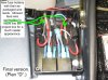
I was going to velcro the box in place but decided instead to mount three nylon cap screws thru the box's floor to act as "legs." The pic below shows one of the legs, plus the ground for the relay triggering circuit.

I did not want to butcher the original harness so I figured out how to wire the relays while keeping the original terminals. Inevitably, it was necessary to slice the original wiring harness sheath open to free up enough original wire to provide the slack I needed to put the connectors inside the project box. If necessary, I could remove the heat shrink insulation and slip the terminals back into the original wire loom receptacle cavities.

I couldn't find any light blue or light gray primary wire locally, so I had to order it. Turns out I bought 5' of each just to get the inch of each that I ended up using for the final version. Plans A & B used #10 feed wires, but Plan C put the mini-fuse holders in the project box, and locally these were available only with #12 leads, so I went with #12 feed wires from the power source.

PLAN D Revision
See this post for Plan D revision:
https://www.xwebforums.com/forum/index.php?threads/wiper-relay-mod-revised-plan-d.14218/#post-290721
So now it comes time to implement it. I think this drawing is the final, I need to check and verify that:
Taking a page from Bob Brown's book, I set a ground rule that I did not want to harm any existing wiring in the making of this mod.
So I pick up a couple of relays and harnesses from the local truck customization store, get a project box from Radio Shack, and start to put it together.
But I hated it. The relays and sockets themselves are cheap, the wiring is chintzy, I have unsightly wires and inline fuses ham-and-egged thru the frunk to the battery, and I can't get the project box to fit the way I want it to.
So I scrap Plan A and go to Plan B.
Different box ordered from the internet, better quality #10 wire, scrap the relay sockets to save space, and after I decide to re-engineer the power distribution system, I can run the power feed up behind the instrument cluster and out the speedo cable grommet, thru the scuttle, and into the frunk right near the original wiper moter harness plug.
But I still don't like Plan B. The small size of the box forces me to put the fuse holders up under the dash. Now that's OK when the interior is gutted, but once the car is put back together, how the heck would I change a fuse? Plus there's still too much wiring outside the box with too many connections.
Come to Plan C. As the saying goes, third time's the charm!
I scour the internet for the project box that's the perfect size, which was a major chore in itself. There are very specific, tight restrictions in that area of the frunk that have to be taken into account---the box can't interfere with the storage of the targa top, and can't interfere with the frunklid crumple post and socket.
And I want maximum length so that I can put the inline fuses inside the box. Even so, there's no room to splice the feed wires to the leads on the fuse holder, which means that the power lead to fuse holder splice has to be outside the project box, something that I did not want but couldn't come up with a workaround.
I was going to velcro the box in place but decided instead to mount three nylon cap screws thru the box's floor to act as "legs." The pic below shows one of the legs, plus the ground for the relay triggering circuit.
I did not want to butcher the original harness so I figured out how to wire the relays while keeping the original terminals. Inevitably, it was necessary to slice the original wiring harness sheath open to free up enough original wire to provide the slack I needed to put the connectors inside the project box. If necessary, I could remove the heat shrink insulation and slip the terminals back into the original wire loom receptacle cavities.
I couldn't find any light blue or light gray primary wire locally, so I had to order it. Turns out I bought 5' of each just to get the inch of each that I ended up using for the final version. Plans A & B used #10 feed wires, but Plan C put the mini-fuse holders in the project box, and locally these were available only with #12 leads, so I went with #12 feed wires from the power source.
PLAN D Revision
See this post for Plan D revision:
https://www.xwebforums.com/forum/index.php?threads/wiper-relay-mod-revised-plan-d.14218/#post-290721
Last edited:

")