Megasquirt/EDIS Project

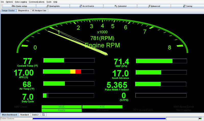
Here's my new car on MS Extra. All going to plan apparently :)

Jacqui.

[ame="http://www.youtube.com/watch?v=ZX8uq1JjkJk"]YouTube - hybrid 1.6 X1/9 turbo engine[/ame]
 
Your lengthy planning really seems like it is paying off. Great to see so much information in such a short time. Wow.

Bummer about the wide band sensor. Hopefully it doesn't cause problems down the road.

Nice work and thank you for taking the time to post up the info.
 
The EDIS is now working. The car starts and runs with the L-Jet and the tachometer is actually working much better than it did before and the engine idles a little better. A timing light shows 20 degrees advance so some how I'm off 10 degrees on the trigger wheel. I'll probably leave it alone and set the trigger wheel offset in Megasquirt to compensate for it.

Edit: Just realized it's not off 10 degrees it just looks like it because I was using my advance timing light when I should have been using using the marks on the engine. The advance feature doesn't work correctly with wasted spark because it sparks twice as often.
 
Last edited:
Pictures?

Matt, I have MegaSquirt 1 running fuel only and purchased the
Daughter card to upgrade to EDIS MegaSquirt 2 if in time I want to. Like your self I wanted only to work on one system at a time, you chose spark first I chose fuel.

Can you show us the pictures of your crank angle sensor, mounting? And also the coil for the sparks, where did you locate it.

Nice job, good write up. Keep it coming.

TonyK.

Grimsby Ontario Canada.

I just now finished mounting the coil. It's not were I would like it to be but it's the best I can do for now. I wanted to mount the coil on a distributor plug coil mount combo so that it would be in the same location as the distributor. Unfortunatly I was unable to get the mount I wanted so I have temporarily mounted it were the Marelli coil had been. The wires are Bosch (P/N 09 303) for a 1991 Escort 1.9L and are almost a perfect fit. When or if I move the coil I will have a set of Magnecor wires made to fit.

IMAG0244.jpg
 
MS uses an on board manifold absolute pressure (MAP) sensor and throttle position as well as an intake air temperature (IAT) sensor.

Yeah, I realize that's the typical way to go. I was just hoping you were gonna be a maverick and use a MAF since I think that's what I'd like to do.

Great project and awesome progress so far. Glad to see you're having luck using the Ford ignition, since that's what I bought for mine. It's funny that so many people diss on Italian electrics because the wiring and connectors for the Ford stuff seem much lower grade than the X stuff was in its day.

Keep up the great work! This has the makings of a Wiki How-To.
 
You can use a MAF but there doesn't seem to be much point in it. I read quite a bit about it and it looks like a huge headache with no significant advantage. However, I do kinda wish I'd gone with MS3 so I could run sequential injection. There could be a worthwhile advantage in performance and fuel economy there.
 
I guess my mental benchmark is the 75HP that a stock 1500 FI car is supposed to put out as reported in most publications of the day (for example, Road and Track road tests).

Back in the day, the car mags didn't dyno the cars, they accepted the manufacturer's quoted horsepower - and that would always be at the flywheel, not at the wheels. If Matthew was quoted power at the wheels, that's the entire discrepancy right there. (They did do 0-60, quarter-mile, skidpad, and the like... but those tests are both less expensive and way more fun).

Also, tuning that raises torque below the peak of the torque curve won't show up as increased horsepower, but makes a huge difference in the usable power - and Matthew's torque curve is impressively flat.
 
Long Day

Bulding a wire harness is extremely tedious work. I did get quite a bit done today but not as much as I hoped.

IMGP0146.JPG


I don't need the thermo time switch any more.

IMGP0141.JPG


So I took it out and replaced it with a Honda oil drain plug.

IMGP0142.JPG


Here is the TPS installed

IMGP0143.JPG


And the IAT sensor.

IMGP0144.JPG


Here is the MS unit mounted in the spare tire well. I'll need to move it a bit because it turns out I can't plug in the serial cable where it is mounted now.

IMGP0145.JPG


Here are some pictures of the wire harness install in progress.

IMGP0147.JPG


IMGP0150.JPG


And here are some pictures of the engine compartment portion of the harness 95% complete.

IMGP0153.JPG


IMGP0152.JPG


IMGP0154.JPG


IMGP0155.JPG


I still need to install and wire the idle valve and do most of the wiring in the spare tire area. I'm not sure if I'm going to work on it tomorrow. Unless major problems come up I should have it running be next weekend at the latest.
 
Controller location.

Matt, take a look at these pictures. This is where I mounted the controller, fuses and fuel pump relays. Remember my car is a 79 carbed, so I need to install a pump and tank to raise the fuel above the injection pump. I have 1 low pressure pump to keep the bump tank full of fuel and below the bump tank is the fuel injector pump.

The first picture is done on the Mock Up body, the second picture is installed in my 79 X. You have the cable and control close to that location and could just turn it around and have it out of the way.


Uploaded with ImageShack.us


Uploaded with ImageShack.us

TonyK.

Grimsby Ontario Canada.
 
Finished the Wiring in the Spare tire Area

IMGP0158.JPG


IMGP0159.JPG


And it runs!:dance2:

First_Start.jpg


The engine started almost instantly like I hadn't even done anything. I was a little surprised by that. Obviously it's going to need some tuning but I don't have time for that today. Also, I still need to move the MS unit, install and wire the idle valve and button up a few things in the engine compartment.
 
Congratulations! Looks like some nice quality work.

Now the real work begins.

I like the power distribution block you're using. Details/sources?
 
I like the power distribution block you're using. Details/sources?

The fuse block is a Blue Sea Systems six fuse unit with ground buss. I picked it up at West Marine for $45. I'm using the same unit without ground buss up front for the headlights. The Blue Sea Systems panels are the nicest ones I've been able to find. They are vastly superior to the fuse panels that the auto parts stores carry.
 
What software is that showing the gauges? Looks a lot different than the Megatune I have on my Netbook.
 
The fuse block is a Blue Sea Systems six fuse unit with ground buss. I picked it up at West Marine for $45.

Thanks Matthew! Those are much nicer than the audio power distribution blocks I was planning on using. Jamestown Distributing has them on sale right now, along with free shipping on orders over $50 (coupon code SPRINGBOARD), so I might have to pick some up.

That's what I love about threads like these where someone is doing a really nice job of something-- there are always ideas to steal. When you have time, I hope you'll add more documentation to the work you've done so far. I've done this kind of stuff before but it's nice to learn from others' experiences. And I think it'd be invaluable for less experienced folks wanting to tackle this upgrade on their own.

Cheers,
 
I know I've skipped over a lot of detail but I will get back to it eventually. I really wanted to get the car running this weekend so I wouldn't have to push the car in and out of the shop every day this week.

Anyway, I installed the A/F ratio gauge and found that the gauge and MS read completely different. I was able to play with the VE table and spark table to get the car running pretty good but I still don't have lambda control. I had forgotten the part in the LC-1 manual that stressed how important it is to ground everything to the same spot as the ECU and I didn't do that. I think that may be the problem. I'll rewire the ground and see what happens. Also, my tach doesn't work even though it's wired to the EDIS coils the exact same way it was before I installed the MS and it worked then. It kinda wants to work ever once in a while but it's mostly just dead.

I drove the car a couple of blocks down the street and even got on it a little bit and it runs really well maybe better than before and I have done almost no tuning so far.

I wired the idle valve but haven't installed it yet. I plugged it in but it doesn't do anything even though MS is showing an output. despite these problems things are going much better than I expected.
 
Okay, the 02 sensor is working now. There are three steps to setting up the sensor. You have to set the type in the project properties and under EGO Control in the basic setup menu. After that you have to "calibrate AFR table" in the tools menu. That was the part I missed. Once that was done it works perfect.

The tach is really annoying. If I unplug it and plug it back in it works for a few seconds. I've heard these things are a total pain to make work properly and I really don't feel like messing with it right now. If anyone has any ideas how to make it work that would be great.
 
how about fitting individual throttle bodies?

More air is coming in and more power will be produced
 
Back
Top