lookforjoe
True Classic
11/21 - installed Volvo 20lb injectors (94-97 850 NA) 0 280 155 746 - couldn't get better than 17 mpg in mixed driving with the larger injectors, even with revised fuelling constants.
11/28 - with the lower volume injectors & fuelling constant reset to LH2.4 NA default, I have mpg of 24 in mixed driving.
Still have a warm up period low idle issue. Have to figure that out next.
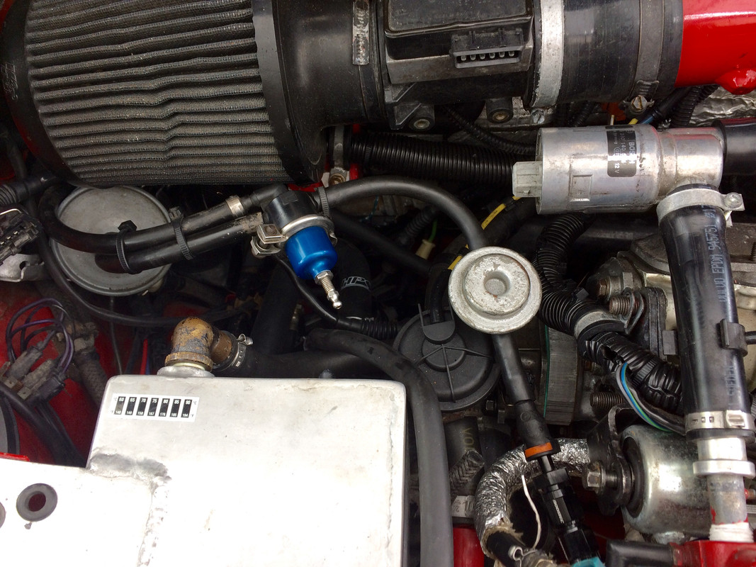
EDIT: Forgot to include the completely new fuel rail I made back in Oct:
Fittings: 1) Fragola 496206BL Aluminum 45 Degree Female Coupler Swivel Adapter -6 AN and 2) BOOSTEC 5/16" male to -6AN Male Push On/Quick Connect Fuel Adapter Fitting (under CSV feed line)
11/28 - with the lower volume injectors & fuelling constant reset to LH2.4 NA default, I have mpg of 24 in mixed driving.
Still have a warm up period low idle issue. Have to figure that out next.
EDIT: Forgot to include the completely new fuel rail I made back in Oct:
Fittings: 1) Fragola 496206BL Aluminum 45 Degree Female Coupler Swivel Adapter -6 AN and 2) BOOSTEC 5/16" male to -6AN Male Push On/Quick Connect Fuel Adapter Fitting (under CSV feed line)
Last edited:
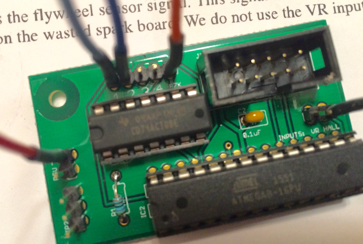
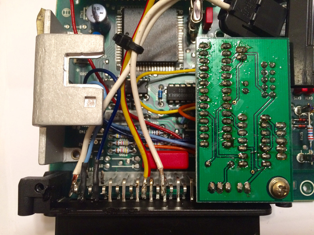
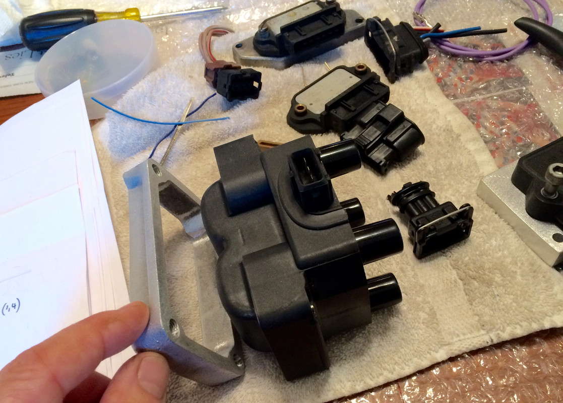
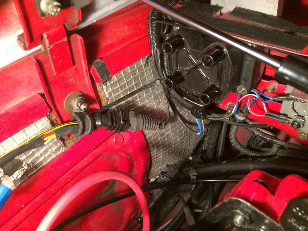
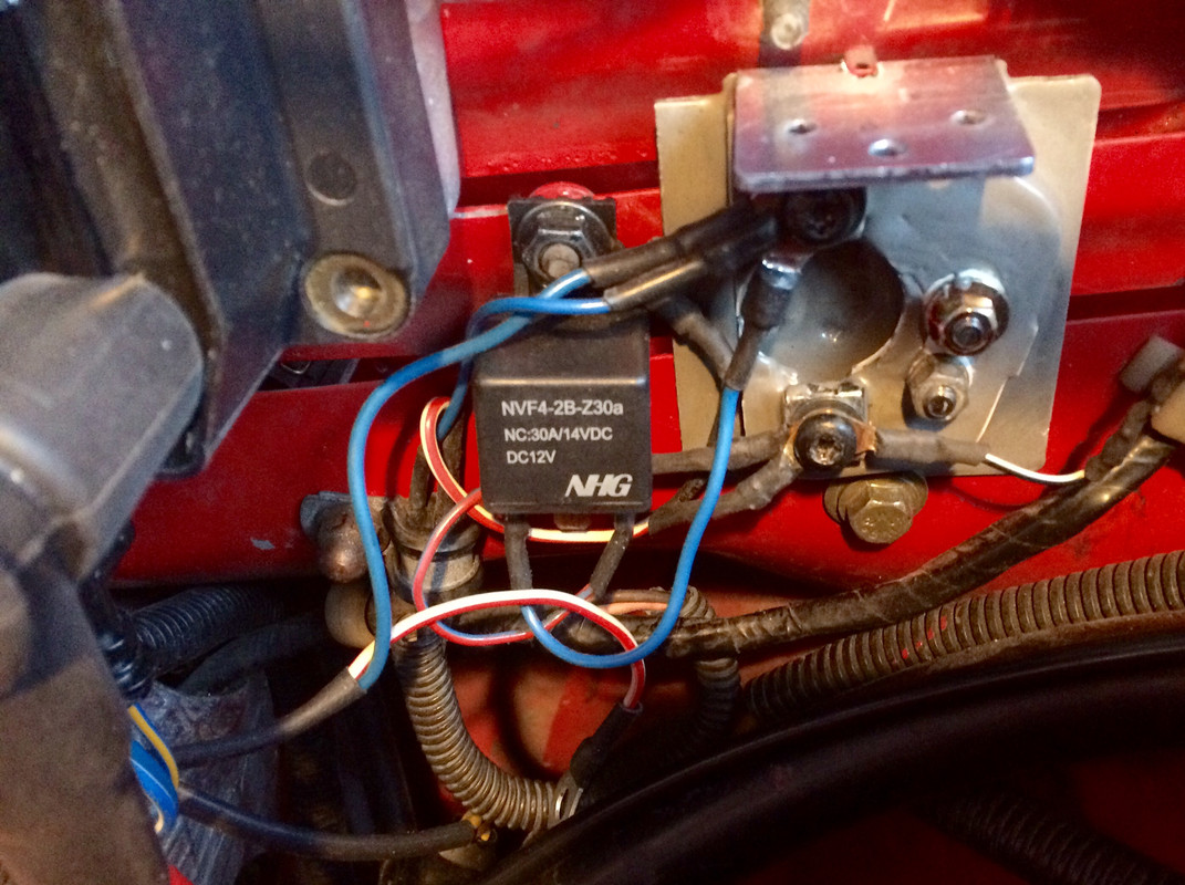
") No more dist, cap & rotor. The LED I added to the cluster will provide visual indication of knock - I'm still waiting for my Dutch friend to have time to work on the data logging routines. He is very methodical & is building a test bed with EZK components to run his routines.
No more dist, cap & rotor. The LED I added to the cluster will provide visual indication of knock - I'm still waiting for my Dutch friend to have time to work on the data logging routines. He is very methodical & is building a test bed with EZK components to run his routines.