Melted Piston.

Thanks for the suggestion.

What I found today, after rewiring the EZK module and power stage switched supply to a relay fed by a dedicated fused (30) coming right off my main LH harness - which attaches directly to the battery cable at the starter. The coil feed is now used to only supply current to the coil, and to the switching leg (86) of the Volvo "J" relay (5 pole, 30A output on 87, 87a) this delivers a steady voltage over 14v.

X19_0369b.jpg


So, after all that, I ran it & checked voltage at the relevant points, and once warm, voltage to the stock pink wire drops below 13.5v, which triggers the surge condition. I added back the supply line that was previously feeding the power stage and ECU, which brought the voltage up closer to 14v, and surge went away. I cannot leave it wired that way, as it creates a loop that disables the ignition key ;)

So, the actual problem is voltage drop to the ignition coil.

I can run a new line from 87a on my dedicated relay to the coil, and that should be the end of it.

EDIT: I think I'll cut the pink wire inside the spare well area, and splice the feed from the relay at that point - that way I don't have to add any more wiring, and the switched coil feed will no longer be subject to variances caused by all the other devices on that circuit. Just have to find it....
 
Last edited:
But here is one version of a good stabilizer ...
You can find all kinds of these on eBay with a variety of current capacities.

In looking for a stabilizer/regulator, it seems that there are few that can handle anything over a few amps. I believe that the coil could draw as much as 15A, given the low resistance of the primary winding (.6 - .9 ohms). I have found one that claims 150W/15A, but it requires bridging the Vout ports as each one is only good for 6A.

http://www.ebay.com/itm/321566164423

!B2Vn1!Q!mk~$(KGrHqEOKjsE)LezpV0rBMiEPRvyM!~~_12.JPG


I'll try switching the supply first, and consider this as a last resort.
 
Ignition current

In looking for a stabilizer/regulator, it seems that there are few that can handle anything over a few amps. I believe that the coil could draw as much as 15A, given the low resistance of the primary winding (.6 - .9 ohms). I have found one that claims 150W/15A, but it requires bridging the Vout ports as each one is only good for 6A.

http://www.ebay.com/itm/321566164423

I'll try switching the supply first, and consider this as a last resort.

In my experience, unless you're using an MSD multi-spark ignition (or the likes) at a sustained high RPM, I've never seen a stock ignition consume a constant 15 Amps. Worse case for a Bosch X1/9 ICM is about 8.5 amps at stall when the points are closed, but it's a whole lot less (on average) when the engine is running normally.

But let's assume you're using 15 amps peak for your ignition, you can add a measure of stable surge current by adding a large value capacitor. My concern would be the average current draw across the full operating range, sustained. You'll need to know that when deciding on a power supply.

Think about this Hussein, 15 amps at 12V = 180 watts that your ignition wire, rotor, and plugs are dissipating. That's a whole lot of power for a spark.
 
The system is a stock Bosch EZK; control module (ECU), power stage, hall effect, coil, cap, rotor, wires, plugs.

I wouldn't expect it to draw that many amps, but I can't find any literature that actually defines what to expect. All test values are simply resistance values or continuity over respective aspects of the system.

I'm hoping that moving the switched feed to a dedicated supply will be the end of it. I'll know tomorrow.
 
After some revisions I have a working solution. First, I had simply cut the pink wire in the spare wheel well, used the feed end from the switch to switch the relay coil, and fed the output (87a) to the other side of the pink wire that carried on out into the engine bay to power the coil.

The problem with this setup (I found after much back & forth) was that using the same (2 pole output) relay for the EZK/powerstage, and the coil created a back feed to the ignition switch that prevented the engine from turning off with the key.

I removed the EZK/Powerstage feed from the relay, and simply attached it to the (switching side) pink wire along with the leg feeding the relay coil. With that, all is well. I have 14.5v at the coil during cold start/warmup, and 13.8-14v when idling (850rpm) warm.

No more idle surging, and the engine idle is no longer effected by the use of headlights, cooling fan, blower fan, reverse or brake light operation. I'm happy :)
 
Last edited:
Huzzah!

Well done Hussein! It was just a matter of time till you figured it out. :headbang: :excited: :thumbsup: :D: :woot:

After some revisions I have a working solution. First, I had simply cut the pink wire in the spare wheel well, used the feed end from the switch to switch the relay coil, and fed the output (87a) to the other side of the pink wire that carried on out into the engine bay to power the coil.

The problem with this setup (I found after much back & forth) was that using the same (2 pole output) relay for the EZK/powerstage, and the coil created a back feed to the ignition switch that prevented the engine from turning off with the key.

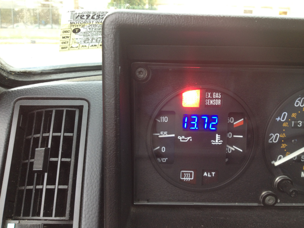
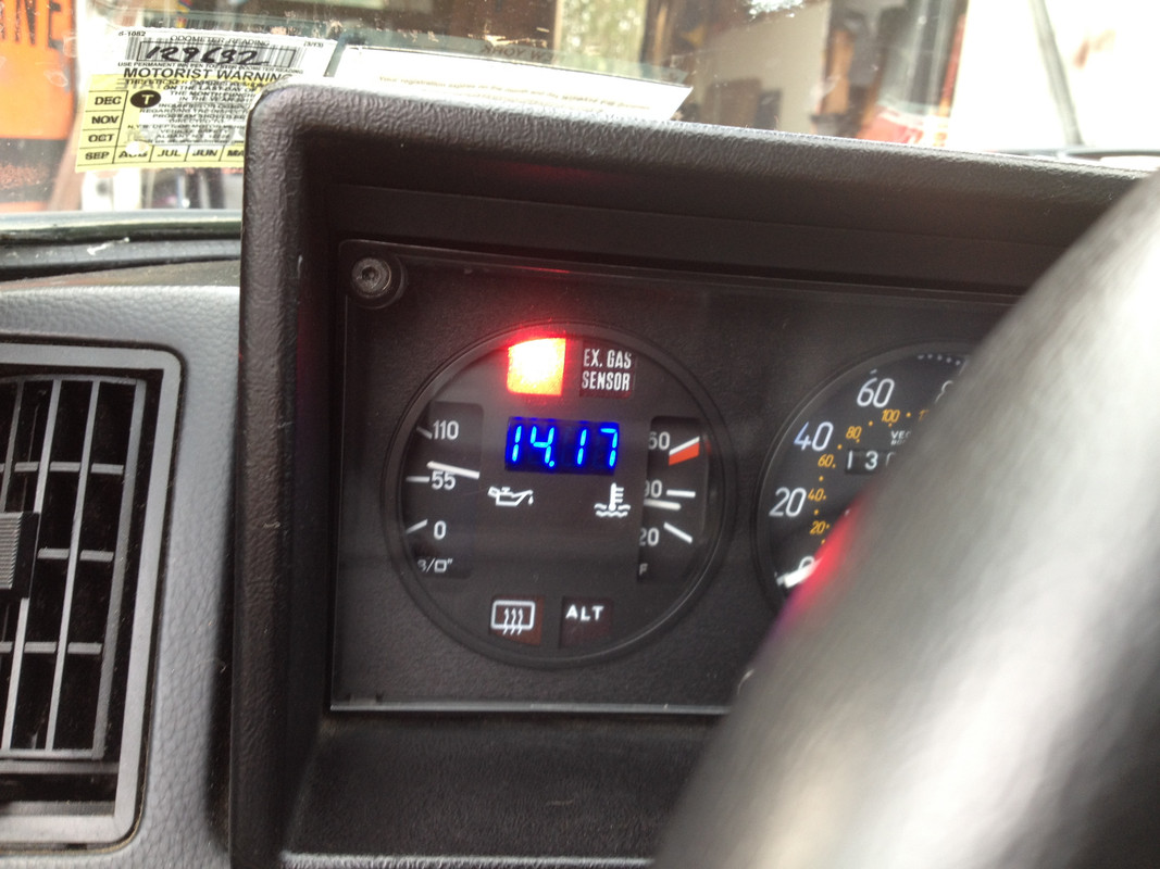
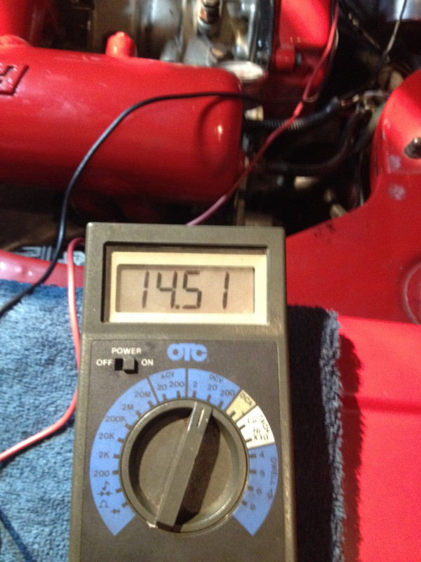
I removed the EZK/Powerstage feed from the relay, and simply attached it to the pink wire along with the leg feeding the relay coil. With that, all is well. I have 14.5v at the coil during cold start/warmup, and 13.8-14v when idling (850rpm) warm.

No more idle surging, and the engine idle is no longer effected by the use of headlights, cooling fan, blower fan, reverse or brake light operation. I'm happy :)
 
Installed a GM CS130 alternator. I like the idea of the 'sense' feed to the regulator that Tony had mentioned in some other threads.

Even with the Fuel & Ignition system isolated, I've not been happy with the voltage drops when lights, heater fan, brake lights, etc are in use. God forbid you're stuck at a long light in the cold & wet at night, when EVERYTHING is on.

So, I found a new AC Delco alternator on eBay, that ended up only costing $32, shipped. :)

Cut down mount ears

X19_0369.jpg


Installed.

X19_0369a.jpg


X19_0372.jpg


Using a PK 1300 Continental belt, the K050523 belt was slightly to long.

There is no adjustment at the alternator, the alt pivot ear is too close to allow the alt to swing. That's OK, since I have the AC compressor pivot to take up slack.

I could have welded a new ear below the existing,which would provide casing clearance, however that would potentially create alignment issues, so I decided to just go with the AC as belt adjuster.

With the engine running (warm, idle) the alt puts out just under 14v, with only the "lamp" (exciter wire) connected.

X19_0399.jpg


With the 'sense' wire connected to the stock coil feed circuit (since the headlights, cooling fans, etc are all switched off that)

Over 14v, and the regulator compensates very rapidly to any current draw

X19-0347a.jpg
 
Last edited:
That's great Hussein and about what my k20a2 puts out. Where does it sit with everything on? I haven't seen below 13 volts (yet) and I would bet you don't either.
 
That's great Hussein and about what my k20a2 puts out. Where does it sit with everything on? I haven't seen below 13 volts (yet) and I would bet you don't either.

With the alternator sense wire connected to a load circuit, I'm not seeing under 14v, except for an instant when initial load is placed on it.

This is with lights, blower fan, AC, cooling fans & hazards, brake lights at idle :excited:

X19-0347.jpg
 
Last edited:
:excited::excited:

With the alternator sense wire connected to a load circuit, I'm not seeing under 14v, except for an instant when initial load is placed on it.

This is with lights, blower fan, AC, cooling fans & hazards, brake lights at idle :excited:

039F6CBA-B02C-46BC-B42F-81743FBAF4A0_zpstkpyys22.jpg
 
Is that your oil pressure at idle warm or cold? My k20 oil pressure is below 55 when warm/idle. Wondering if yours is normal for 1500 Fiat? I don't recall the PBS engine being over 55 unless cold. Maybe my sender needs to be replaced...:hmm:
 
Finally found the problem between the Volvo & Saab versions of LH2.2.

The wiring to the MAF itself is scrambled from one version the next, which was causing the burnoff mode issue when I plugged in the Saab ECU & MAF

Still haven't found an actual Saab wiring schematic, but Volvo LH II & Porsche LH2.2 both used metal case MAFs, and the wiring varies as follows:

Volvo LH2.2...... Volvo LH II...... Porsche LH2.2
MAF................. MAF................ MAF
1 - (-).............. 1 - ECU 8..........1 - ECU 8
2 - ECU 6.......... 2 - ECU 9 (+)
3 - ECU 7.......... 3 - ECU 6..........3 - ECU 6
4 - ECU 8.......... 4 - (-)
5 - ECU 9(+)....... 5 - ECU 7..........5 - ECU 7
6 - ECU 14......... 6 - ECU 14........ 6 - ECU 14

I'll make a pigtail off the Volvo MAF connector, to feed the Saab version, then I can give it another go.
 
Last edited:
Is that your oil pressure at idle warm or cold? My k20 oil pressure is below 55 when warm/idle. Wondering if yours is normal for 1500 Fiat? I don't recall the PBS engine being over 55 unless cold. Maybe my sender needs to be replaced...:hmm:

My sender is a Volvo/VDO - the gauge reads in reverse :rolleyes2:

At some point, I need to make a inverted gauge face to remedy that
 
Thanks Karl.

I've already looked at those, and many more. The only ones that actually describe the pinout and terminal pins are the Porsche related diagrams, and none are 'official'. I have to 'assume' it's the same as Saab LH2.2, which is NOT the same as Volvo LH2.2 - it matches LH II (MY83-84), which Volvo discontinued in MY85. Honestly, the metal case MAF really should have clued me in to the fact that the wiring between the two would be different, but it is described as LH2.2 in all the Saab literature & fault tracing (like the PDF you linked - I've read that several times through, trust me).

Presumably vehicle manufacturers like to make sure people don't go swapping parts between models of different product lines willy-nilly, can't imagine Bosch would go to all that trouble of their own accord :rolleyes2:
 
thread mining

2 things... i had some one ask about thermo adadaptors for tipo heads... and this thread sums it up for home made.

and secondly... Hussein, did you ever get this to a dyno? do we have more than just an estimate...I.e. real world performance number, like it would take X seconds to climb this hill and top out at xxmph ...l and now does Y sec and YYmph (for example)

SteveC
 
Back
Top