Uno turbo info
Here's some other info I've collected re Uno's-good reading, use what you want with a grain of salt:
1.The UT system has several versions, but the Mk1 setups have three operating 'modes'... tickover, normal running, and default.
The default mode is very limited in the Bosch/Marelli system, it occurs when the ecu 'sees' the sensors, but the value returned by one is outside expected values (can't be read off the 'maps' in the ecu). Because there are a very limited number of sensors used, its unusual to experience this 'default' mode. One of the classic areas that can cause 'default' is teeth counting of the flywheel. If you are using an X1/9 flywheel for instance with the wrong number of teeth. or the sensor is not sending every tooth due to poor distance adjustment. The default mode results in a maximum engine speed between 900 and 1100rpm.
On the other hand at tickover in this system the ecu does nothing, its main tasks associated with the air corrector/ plenum pressure, injectors and timing only begin when a change from tickover is detected.
Everything can cause the engine to stall when moving off tickover. The difference in diagnosing what the cause is depends upon when and how its stalls.... in effect which engine function has failed.... and its difficult to be precise so everything is suspect.
If it stalls instantly when moving off tickover its not only an ecu electrical fault that's suspect....
any pressure changes can cause it (e.g. ecu vacuum pipe, air corrector valve, plenum/ pipe leak)
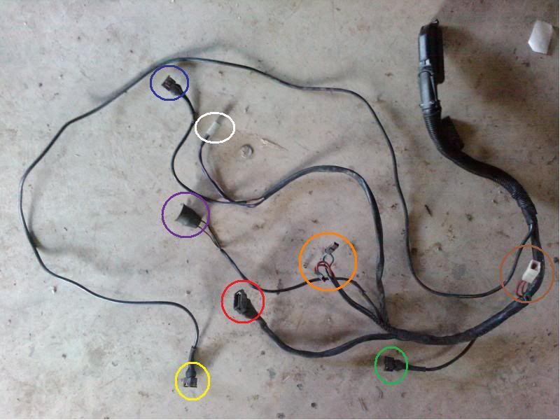
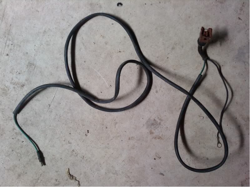
any fault in the loom, earths are potential cause but the junction boxes on the nearside of the donor engine bay, including the coil are highly suspect.
For reliability replace the whole engine bay loom.
any assumptions made about connecting the fueling and fuel pump into the exxie system. A full flow return through the pump. It's the simplest Electric pump height is unlikely to cause a cut off, but it should deliver flow from ignition onwards. Are all the UT features for pressurising included?
The air corrector is a subject itself..... response/ flap operation system to check, with pressure in the fuel rail and full fuel return through the pump. and critically its relay box.... make sure you can atleast substitute with a new relay. The whole setup is regulated by the plenum pressure, and the mechanical/ electrical returns come from the position of the air corrector.... the wiring and relays here must be high on the suspect list.
Pipes, there are three areas that can cause the same symptoms (as an electrical fault) on the air supply circuits. A hole in any of the short main pipes can cause the engine to stall from tickover. Make sure you have a good diagram of the pipes... if the car stalls coming off tickover then there are two 'favourite' connections leading to the input side of the turbo..... the short difficult to get at pipes can cause it, but you would normally get some revs (about a second or two up to 1500rpm) before it stalls.
Its less likely to be the re-circulatory valve and circuit - which doesn't cause a stall but stops boost building.
I'd discount to last the turbo/actuator/ cracked housing/ exhaust manifold/ and the inlet manifold cracked/ vacuum takeoff open. As
Take a jumper cable and connect it to the engine
there's no electrical/ sensor monitoring of the exhaust side of the system (ie lambda) to stop the engine from running.
You're left with a tricky diagnosis - precisely HOW it stalls and at what revs.... there is a small difference between - how instantly it stalls.... if it looks like an electrical fault, a load fault (no torque due to pressure leaks), a fuel supply fault (or injectors not firing).... a cut out from default mode.... a cut out from the ecu because of no signal (from the air corrector relay?)?
they are close together... you can't assume its an electrical/earth fault.... on the other hand its very difficult to find a loom wire break/ won't take a high impedence.... you may be checking/ substituting the sensor, but the UT engine bay wiring is often the problem itself....
lastly are you SURE you've brought over all the essential UT components, and not just assumed that the original exxie stuff will do? Where are you interfacing the fuelling, and the loom/ fuse box.... are you sure its not in the loss of additonal UT wiring/ relays to the Bosch box for instance? For most of this stuff, I assume you've wired an alternative supply/test though.
The 'bottom line' is you must not focus on an ecu/electrical fueling fault just because its the usual explanation for this symptom - on the UT its not the main cause of this sort of behaviour....
to go into detail we need to know more about what and how you've installed it (esp. the loom & electrics). Are you using a UT wiring diagram (not x1/9)? If you've got one start again with the relays positioned outside the main fuse/ relay box first.
You need to take a fresh and broad look at it... and suspect the way you've wired it up, and the wiring itself. Don't leave out the other candidates listed above because you think it must be electrical!
2.
Ignition Relay
Terminals are for the following:
TD (= 1) detects that the engine is running by seeing the ignition pulses. If the engine stalls the relay shuts off the fuel pump after a few seconds.
15 is the 12 V feed from the ignition switch.
30 is the permanent 12 V feed from the battery.
31 is ground.
50 is the override from the starter, this overrides the relay's pump shut-off function during cranking only.
87 is the feed to the fuel pump.
87b is the feed to the warm up idle valve. (87 and 87b are internally connected)
You should be able to find a similar relay from VW and Audi models of 1980s - 90s vintage, as they used similar Bosch FI
3.
[FONT="]OK I would like to start by stating that the Uno Turbo conversion is very well documented but I have found that the "tuning" side of it is mostly garbage and that the conversion isn't the no-brainer it should be.[/FONT]
[FONT="]I've blown up 4 engines through experimentation and in some cases dumb-ass obstinacy but I think I can honestly say that I know where most of the pitfalls are now.[/FONT]
[FONT="]The Uno Turbo engine *is* the 1500 block with an EFI head. There are internal differences but externally there is very little to tell them apart. The MkI exhaust manifold is the most suitable but essentially limits the user to the smaller IHI turbo instead of the later Garet unit - personally I don't believe this is a bad thing though.[/FONT]
[FONT="]My criticims of the documentation I've used is that the X1/9 cooling setup is barely adequate for a turbo install and that is before you start tuning it up. The Uno Turbo coolant expansion tank is essential where it is frequently described as ugly and unneccessary - without it you *will* cook the engine. A fabricated alloy version of the tank cost me £150 to have made and delivered to my door - far superior to the plastic original and it looks the dogs ********. In order to improve the cooling I fitted an electric water pump and got it wrong. The pump *must* fit inbetween the thermostat housing and the old waterpump otherwise you will cook the engine (sound familiar).[/FONT]
[FONT="]The stock Bosch management system is passable and has some nice touches but in terms of extracting potential it is again inadequate. I've opted for a DTA Fast system and I now have a fully mapped system that can be adjusted while I drive the car. Expensive but very, very good! It also has the advantage that you don't have to **** around with fitting the crank sensor.[/FONT]
[FONT="]In terms of tuning the Uno Turbo needs a very large air filter surface area, the cheapy K&N cone filters are not big enough and tend to starve the engine a bit. The exhaust system only needs to be a pipe to get the exhaust exit outside the periphery of the car, the turbo makes it very, very quiet if you fit a silencer box. The noise testers tend to die laughing whenever my race car rolls up in the test bay...[/FONT]
[FONT="]I haven't had an opportunity to mess around with camshafts but I have been told from a number of different sources that the *stock* european 1500 X1/9 camshaft is one of the best you can find for the MkI UT engine and it would cost very little to source (here).[/FONT]
[FONT="]The fuel pump that comes as standard is very sensitive to it's proximity to the fuel tank and the height it is mounted at. I have been forced to use a lesser Facet pump to run a swirl pot which in turn feeds the high pressure pump. Failure to pay attention to this detail will result in a lack of piston crowns after a few high speed runs.[/FONT]
[FONT="]The usual documentation for the conversion suggests that it is a good idea to fit the oil cooler on the right of the engine bay (using the rhs duct) and the intercooler on the other side (using the lhs duct). This is absolutely useless and just ends up filling the entire engine bay with very hot air. See below for more thoughts on cooling.[/FONT]
[FONT="]The stock OEM headgasket is *very* good, the only other gasket worth having is the SPESSO competition gasket but after much experimentation I can honestly say that it offers no major benefits except that it is easier to remove when the gasket fails. The OEM version literally glues itself to both surfaces making it a real pain but as such is less likely to suffer a minor failure.[/FONT]
[FONT="]There is a major, major problem with the mkI UT engine and that is sourcing piston rings should they ever fail or you need to rebore. The only option is to have some made to spec. The aftermarket ones that are available are as good as junk IMHO. Further to this the block itself has a tendency to warp if heavily abused - this would appear to be down to the turbo itself but I have no way to prove that at the moment.[/FONT]
[FONT="]The early MkI gearboxes are very rugged and you can pretty much swap all the internals straight over to an X1/9 5-speed housing. They use needle roller bearings instead of solid bushes for each of the gears which goes a long way to keeping the synchromesh in good shape. I treat mine like **** while racing and so far haven't managed to do any damage except when the nut came off the end of the input shaft but that is another story and had nothing to do with me
[/FONT]
[FONT="]Tuning potential is enormous. A round figure of 170bhp is readily available without messing internally. On a minor level of tune you can acheive 230-250bhp with the aid of a decent hybrid turbo. On a serious, major expensive level of tune you can get well in excess of 300bhp and nearer 400bhp in some (proven) cases but this requires serious development and the owners of such engines are very reluctant to spill the beans on how they have acheived this. More importantly though is that the engine can be tuned to run at 1.0bar boost instead of the stock 0.6bar very very easily (again this is well documented).[/FONT]
[FONT="]Consider now that the UT engine adds only a very small additional weight to the car (the turbo) yet offers double the power with little trouble. I would say that this is a dream come true for most people. With a bit of diet for the rest of the car you can happily reach 200bhp/tonne. A serious lightweight car would be over 300bhp/tonne with the same engine and I think you all know what that means in terms of performance.[/FONT]
[FONT="]There is however a serious downside to this level of performance from the engine - heat and lots of it. I was forced to fit a triple core aluminium radiator on my car to help it contain and control the waste heat and that was running just 140bhp at 0.8bar. I also used an oil cooler 3 times the size of the stock unit in conjunction with a ram-air style duct. Moving up to more power just means more waste heat and without serious consideration it makes for a very unreliable car. A good 80% of all the development work done on my racecar has been down to improving the cooling capability, the only other thing that has come close in terms of cost was the installation of the DTA system.[/FONT]
[FONT="]
[/FONT]