Head & Cam work...

lookforjoe

True Classic
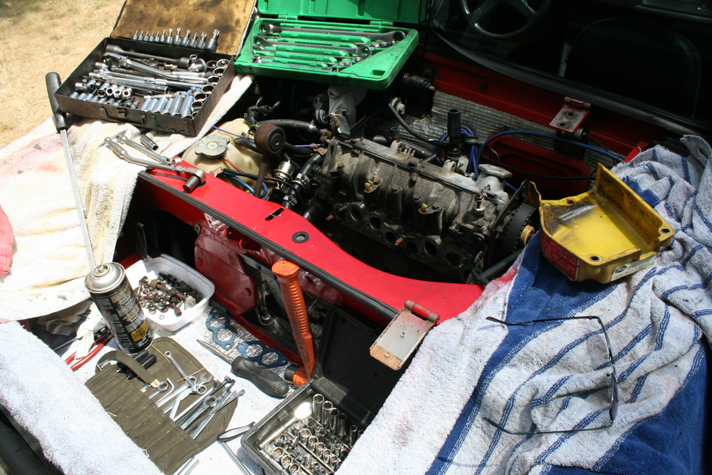
..I bought one of Matt's Cam/CamBox kits a little while back, and decided it was time to get moving on it. I'm leaving for 'Vegas in the AM, so I figured I could get all the head porting & milling, cam installed & shimed while I'm away :D

X19-0904.jpg


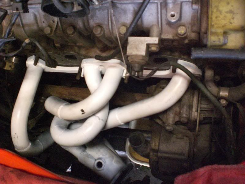
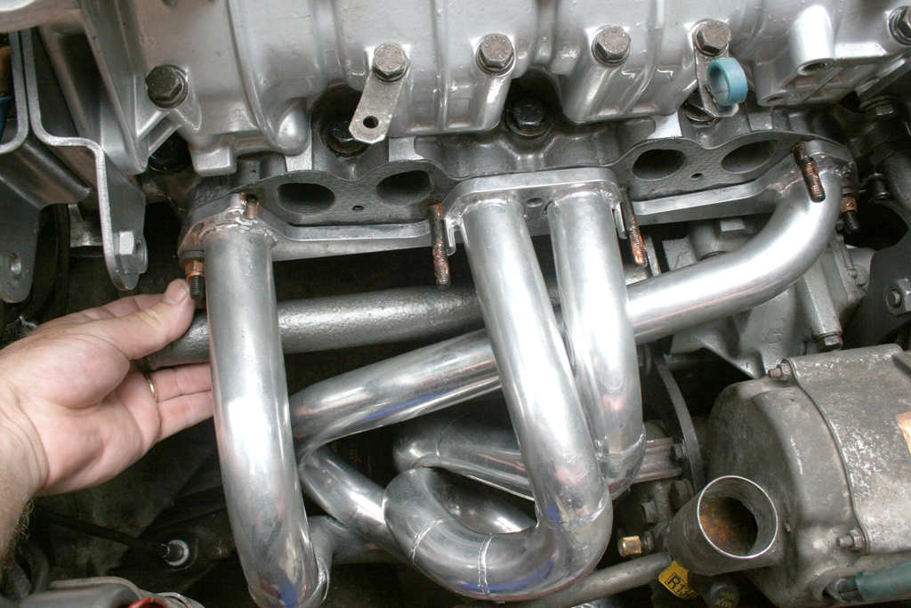
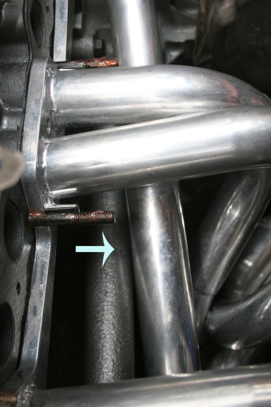
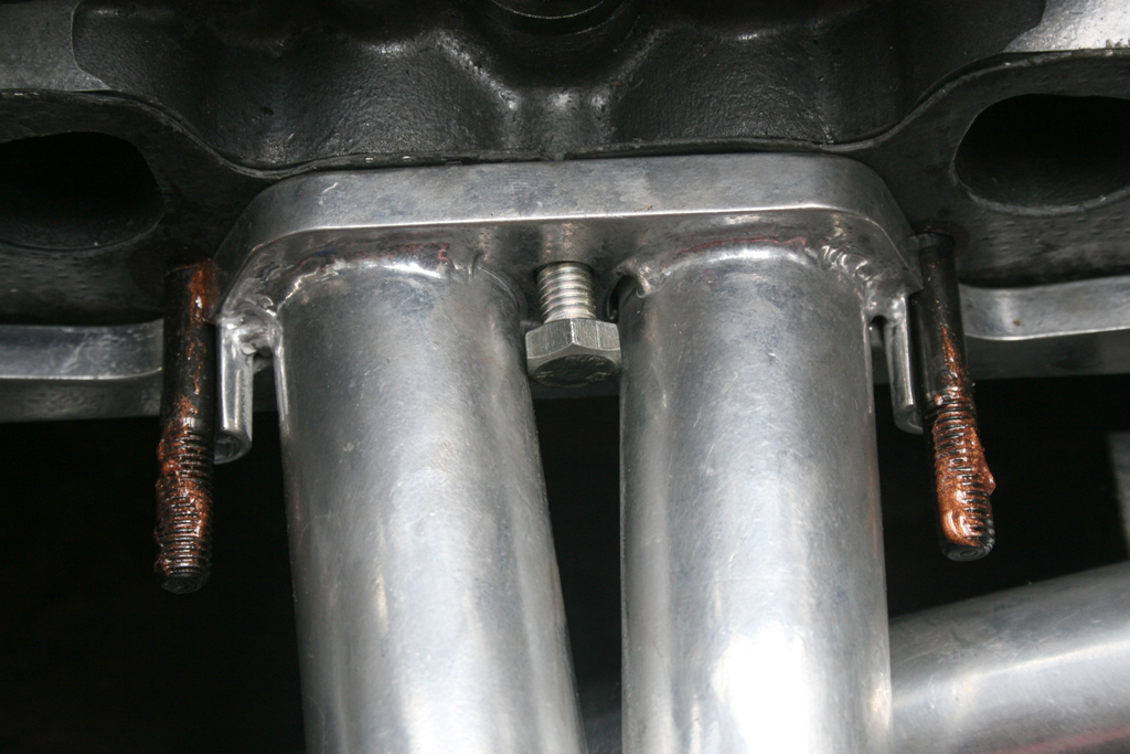
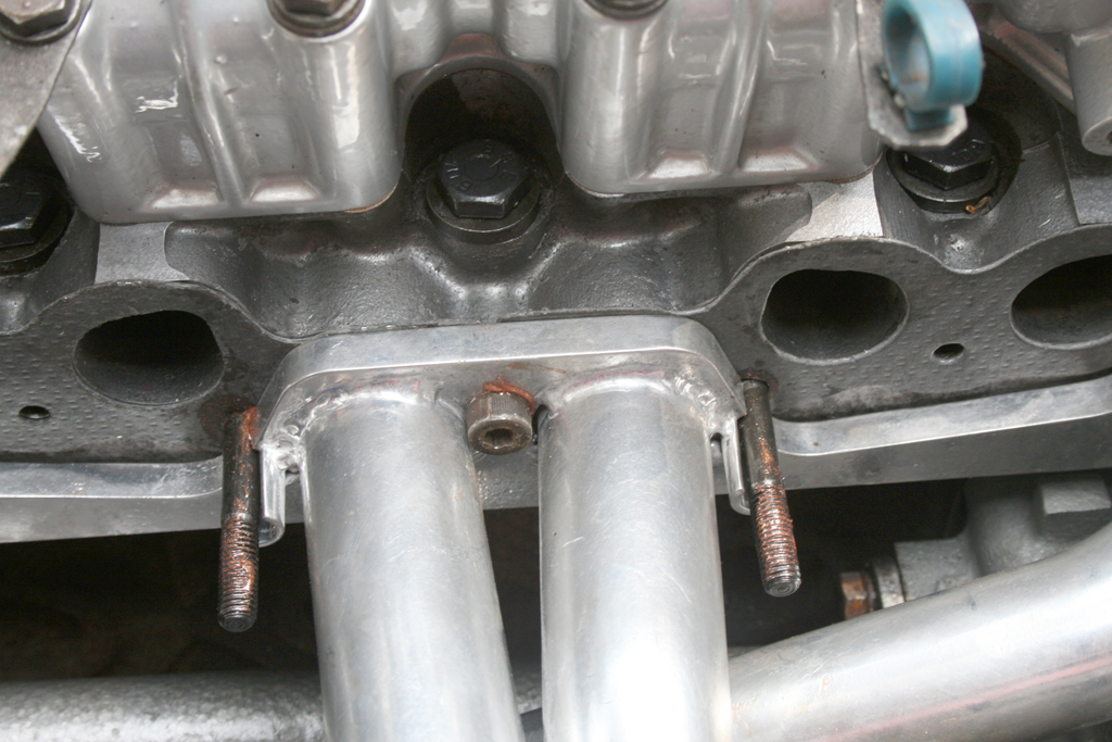
Three exhaust studs snapped, one injector allen snapped, and one intake runner thread stripped. Not too bad, really.

X19-0903.jpg


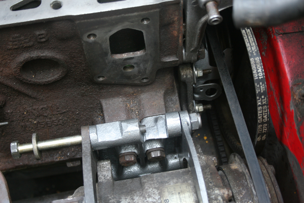
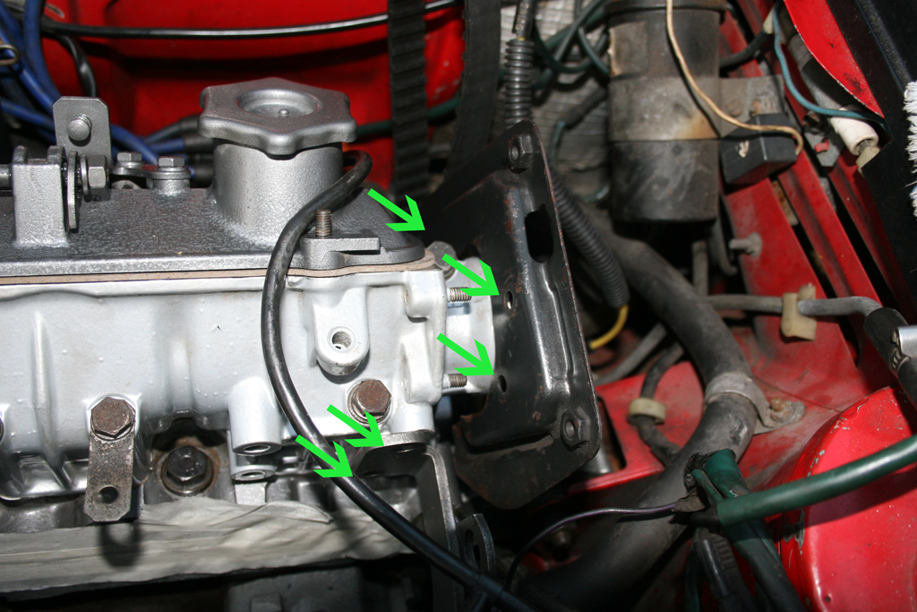
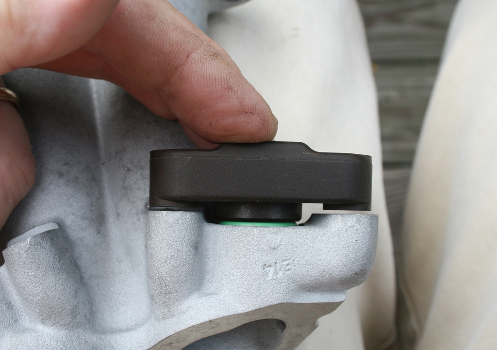
Cam/cam box has been leaking on my new (last fall) timing belt...

X19_0901.jpg


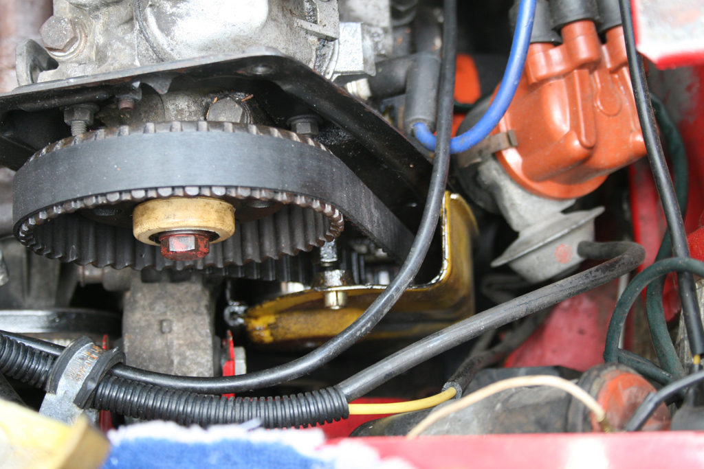
this may have something to do with my sometimes erratic idle

X19-0906.jpg


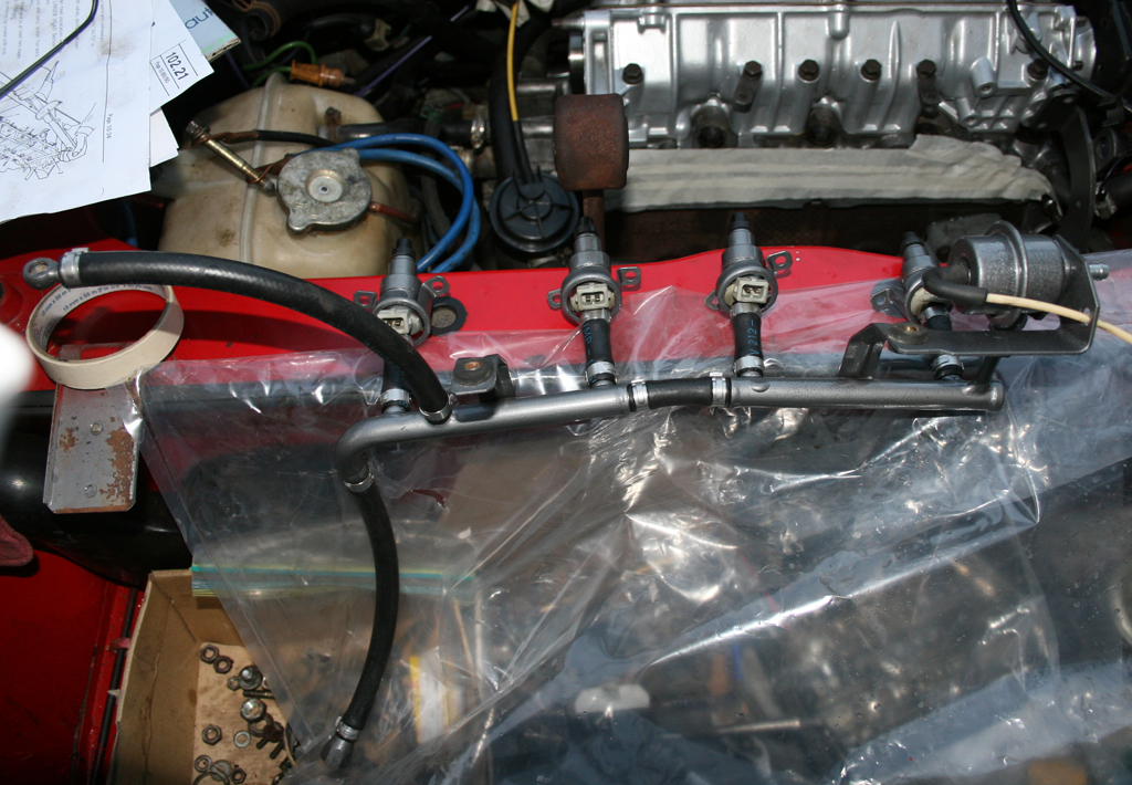
Head doesn't look too bad for 115K

X19_0905.jpg


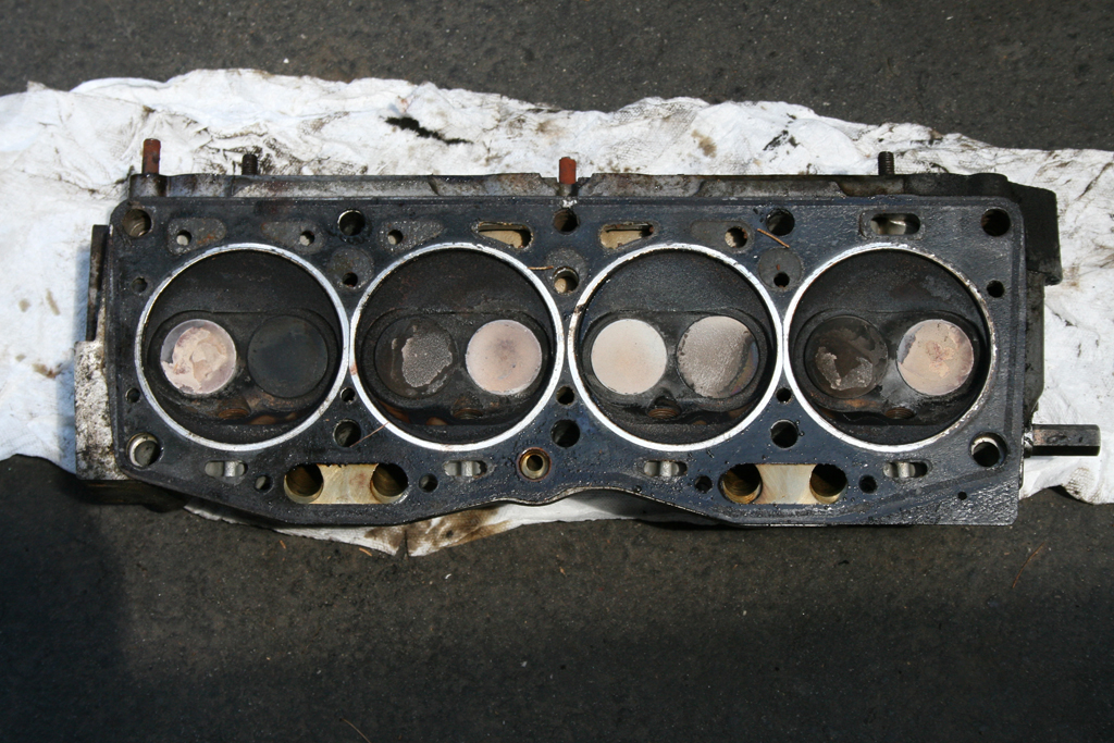
nor do the bores/pistons

X19_0907.jpg


X19_0908.jpg


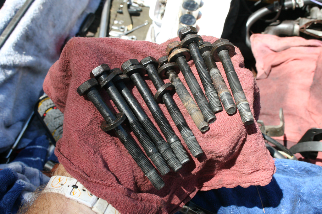
head bolts all have a nice oil coking about 2/3rds way down..

X19_0909.jpg


Car is now tucked away until I get back.

IMG_7454.jpg


Actually, we didn't want it to see the new (to us) freebie that we're driving back & get jealous :rolleyes:

IMG_2205.jpg
 
Last edited:
just ordered one of these....

ceramic coated......

CIMG0909.jpg


.... couldn't bear the thought of putting the stock mani back, esp since I'm making a 2.25" exhaust system.
 
Last edited:
Worked on the X today....

... Head should be ready tomorrow or Thursday, so I started work on the misc stuff. I removed old water pump - no evidence of excess clearance on impeller/housing, but I'm not putting the old one back. Cleaned up & painted water distribution pipe, installed 1300cc belt tensioner.

Removed some material from underside of front engine mount casting, to aid in belt replacement.

Stripped old fuel hoses from rail, cleaned & painted rails: replaced with Volvo 1266500 fuel line & otiker (sp?) clamps. Injectors were cleaned & refurbished by WitchHunter, they actually weren't in bad shape, but pulsed flow has improved from about 5% to under 2% variance.

Stripped & painted cam cover. Ground all casting seams from intake manifold, file & sand tomorrow. Wondering whether it would be worth boring out the throttle housing & installing a larger butterfly...

Removed AC compressor brackets; going to braise captive nuts to forward "C" bracket to aid in future R&R. Going to cut AC base mount cast bracket to allow access to water pump lower bolts.

Exhaust comes off tomorrow in preparation for custom system.

Figured out that the injector & spacer seals are the same as old Volvo "D" Jetronic (72-73), so found those locally, Bayless was experiencing delays in locating them.

I'll add pics tomorrow.
 
Last edited:
Ha... I almost passed out in anticipation...

Finally... the "V" word pops up in the last sentence!

BTW... none of your photos showed up... try re-posting them here!
 
No pics, 'cos I didn't take any yet...

... :rolleyes:

this shows where I shaved the engine mount to ease belt replacement

X19_0913.jpg


this is the modded AC support bracket, allows water pump replacement without further removal beyond the upper cross bolt; nuts for same are now captive

X19_0911.jpg


installing water pump

X19_0912.jpg
 
Last edited:
Got the head back today...

... so I got it back on the car... torqued in 4 stages as per the book..

IMG_7688.jpg


have to elongate these 5 holes to fit the shield & alternator bracket

X19_0915.jpg


the painted fuel rail

X19-0982.jpg


otiker clamps

IMG-7529.jpg


painted inlet pipe to match the car

IMG-0480.jpg


had the manifold bored to accept a 2.25" Volvo butterfly, not cheap due to the awkward nature of the manifold. If I had to do it over, I'd be better off just cutting the throttle section off the manifold & fitting a Volvo 2.25" flange :rolleyes: This has the benefit of appearing stock.

X19_1103.jpg


had to cut down & rethread the Volvo shaft to fit the Fiat linkage & TPS

X19_1102.jpg


used a Volvo TPS bracket pressed onto the shaft housing (removed some material from the housing to make it round) due to the altered placement of the TPS slot on the throttle shaft

X19_1101.jpg


Just waiting for a few parts to finish it up, then I can get the exhaust fabricated.
 
Last edited:
Nice!

Hussein , It's looking good. I'm anticipating the results of the engines performance gain.

I'm in the process myself in moding my head. So yours will be a good measuring tool. Even the hose clamps you used are the same as mine.

Nice touch on the throttle body as well. I've done the same thing on my old Porsche.
 
Yur gettin really sceery Hussein...

Pretty soon yur gonna install a V70 Station Wagon top er even something worse!

HA!

Too bad ya didn't have any dyno figures for the "before" modification... of at least this butterfly mod. Are you increasing fuel pressure or fuel rate of the injectors also? And if so, what are you fine tuning it with?
 
Quality work there Hussein...

And quick too. I like the paint color you chose for the FI rail and I REALLY like AND need that snorkel you have (well, one like it I guess). I need to replace mine and I like how yours looks. I will go and look for that thread...
 
Spacer seals

[/quote] Figured out that the injector & spacer seals are the same as old Volvo "D" Jetronic (72-73), so found those locally, Bayless was experiencing delays in locating them. [/quote]

Where did you find the spacer seal? I was up in Connecticut last week and Danny at Fun Imported Auto and Toys did not have them. Stopped at International Auto Parts on the drive home and they did not have them. Did you get them at a local parts store or from a Volvo parts department. You say "D" Jetronic (72-73) but no Volvo model to reference at some place like Auto Zone.

Thanks
 
Last edited:
Pretty soon yur gonna install a V70 Station Wagon top er even something worse! HA!
Too bad ya didn't have any dyno figures for the "before" modification... of at least this butterfly mod. Are you increasing fuel pressure or fuel rate of the injectors also? And if so, what are you fine tuning it with?

No, it's staying a Fiat body-wise :grin:

Unfortunately, I won't know what the TB increase effect will be, since I've combined the shaved head/porting/cam&shaved cambox/allison header into one move. I have a 3bar regulator I can swap out if it feels like it need sit. I was planning on loosing the AFM flap spring as few turns from the get-go.

On my Volvo, I did one mod at a time, so I could evaluate the changes. I'm going to rely on the butt-dyno with the Fiat.
 
And quick too. I like the paint color you chose for the FI rail and I REALLY like AND need that snorkel you have (well, one like it I guess). I need to replace mine and I like how yours looks. I will go and look for that thread...

Thanks. :grin:

Paint is just Rustoleum hammer finish.

It's 2.75" "J" pipe cut down, with step coupler for AFM end. I use an aluminum braise rod (HTS-2000) to fit the copper pcv/vent tubes.
 
Last edited:
Where did you find the spacer seal? I was up in Connecticut last week and Danny at Fun Imported Auto and Toys did not have them. Stopped at International Auto Parts on the drive home and they did not have them. Did you get them at a local parts store or from a Volvo parts department. You say "D" Jetronic (72-73) but no Volvo model to reference at some place like Auto Zone.

Thanks

Sorry, the injector seals are same as "D" jetronic (140/164e) - the spacer oring I'll probably use is actually same as Volvo CIS outer injector housing seal :960218 (not 947114). I say probably because the 5mm holddown allen bolts I bought are longer than stock, so I may use a thicker wall seal to take up some of the space. The alternate seal I have is a same ID, thicker wall R134a oring. I'll take pics tomorrow & measure the actual seal for you.
 
Last edited:
Seal Dimensions

Bob, it seems the Volvo seal 960218 (not 947114) will only give a little "squish" for sealing...

X19-0918.jpg


..compared to the R134a seal

X19-0917.jpg


...which is closer to the original wall thickness, I believe

X19-0916.jpg


So, 16mm ID 2.75mm wall thickness is what you want to get. I'm sure any autoparts store will have an array of orings by size.
 
Last edited:
Installed the AllisonAuto Header today...

...ended up taking much more time than I anticipated, so it's not all back together & running, but the header & intake spacers are in...

X19allisonHeader0009.jpg


X19allisonHeader0010.jpg


I discovered that to fit the header on an AC car, the water dist pipe HAS to be removed, along with all the manifold studs, there's just no room to maneuver.

Very nice construction & finish on the pipes

X19-0947.jpg


Some side to side jiggling of the header was needed to get the studs back in, and a couple are unusable. I have spoken to Mark & sent him pics, so he can address the issues.

Water pipe must go back before intake runners

X19-0948.jpg


Only a few thou clearance on the water pipe

X19-0950.jpg


02 sensor hits AC line, even after bending line. Ideally the bung will be placed further back up the collector, so the 02 falls between the two lines. I may have to discharge the AC & futz with the line, esp. if I have to swap out the 02 sensor for any reason.

X19-0949.jpg


No way to get a stud or a hex head bolt in here between #2 & #3 runners...

X19-0952.jpg


I used an Allen bolt (CV joint, Volvo AWD fore/aft driveshaft), cut down to length that would clear the runner & still go straight into the head; which means only about 20mm or so threading in

X19-0951.jpg


Allen also used for #4 intake/exhaust due to angle of runner interference, didn't need to cut this one, so it has about 25mm seating in the head

X19allisonHeader0008.jpg


Hopefully I'll have time tomorrow to finish up the intake & get the engine running & timed (it's gonna be loud, I have no exhaust fabricated yet :grin:
 
Last edited:
Excellent information.

Thanks for sharing. Those pictures say a lot.

It might be a good idea to rotate the O2 bung 90 degrees or so on the pipe on the next build.
Also, it would be a good idea (on the next build) to allow enough space for the original bolt to fit between exhaust ports 2 and 3.
Or, plan on a Hex head bolt replacement.
Keeping the pipe away from the AC line would also be a plus, unless it's not as close as your picture shows. :geek:

Otherwise, looking pretty good! :thumbsup:

02 bung can't be rotated as much as 90º, it would cause potential moisture collection issues with the tip, but it could be moved back 10mm or so, I believe.

The low side AC line is close, but not enough to be an issue with the ceramic coating, I reckon. I'll see if I can get a pic through the access panel to show the actual clearance there.
 
Hussein, a bit of advice.....

Don't know whether you have done it, but when torquing down the header and fuel injector mount tubes/lower manifold, put the upper manifold/plenum in place.

There is enough compliance in the mounting of the lower manifold pieces to the head that the studs joining the upper to lower manifold may not line up completely. Very frustrating.

Ask me how I know.

Ciao,
 
Back
Top