lookforjoe
True Classic
Finally got around to installing the A1 Electric Central Lock Kit, along with a remote trunk release, and (Bulldog) BW853 4-button keyless entry system. I installed a cluster from BBrown recently - very nice work on his part.
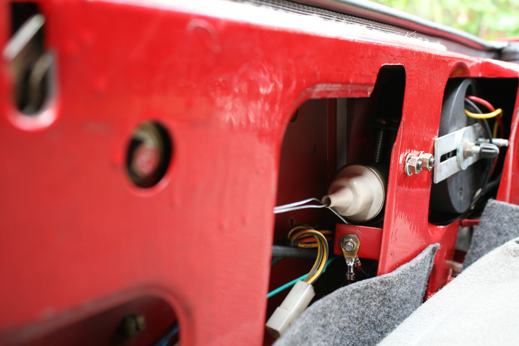
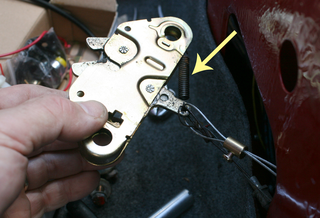
Trunk remote is mounted on left panel so wire is a straight pull

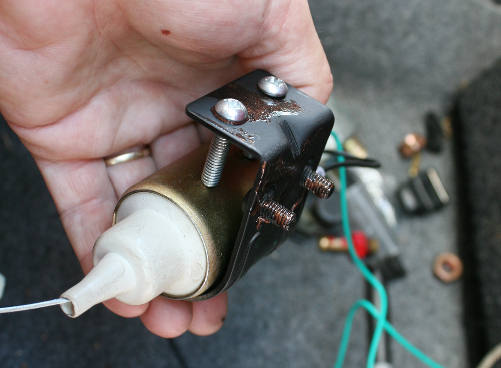
in testing, the remote cannot overcome the heavy spring tension of the lock - I had to remove the 'helper' spring off the lever, then it worked fine

I used the live blue/red feed already present in the right 1/4 to power it - cut the other end * the electrical unit & spliced in the fuse holder & remote release switch, which I also mounted in the central electrical unit cover, in front of the fuse panel (forgot to take a pic).
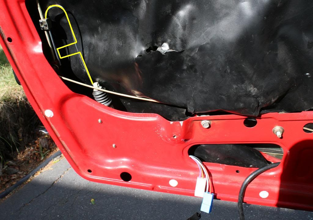
Mounted the central lock motors following the example of someone on here (sorry, forgot who posted the pics). Routed harness through stock wiring conduit. Took out the drip sheet & repaired the visible tear while I was at it.


I taped the connectors outside the inner door skin, since they are not waterproof, I don't want them laying in the door


took the opportunity to coat the backside of the door cards with clear acrylic spray & used velcro to install (recall someone on here mentioned doing that), getting rid of all those clips that always break.
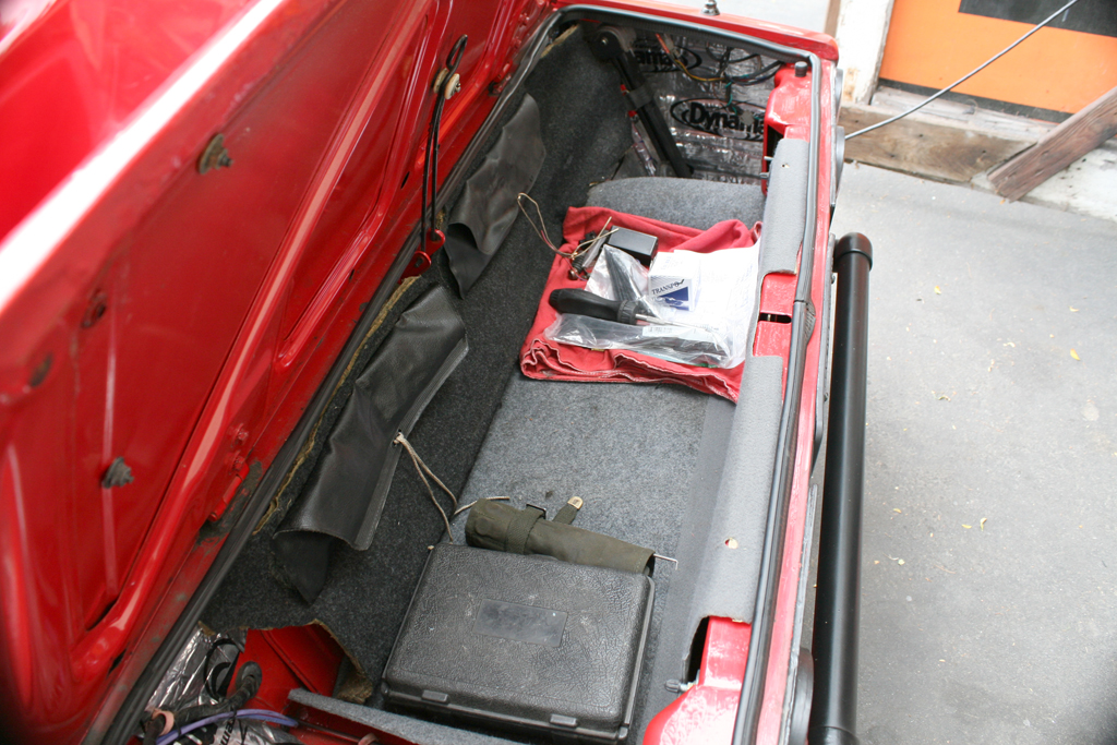
Main relay & harness is attached to top of central electrical unit, to keep all relays & fuses in one place.


Keyless entry system required adding THREE additional relays, one for the trunk remote, one for the interior light function, and one for the flashing parking lights function (that was a PITA figuring out which wire would feed just the parking lights & not trigger the H/L motors). I tapped into all the feeds at the CEU, so as not to have extra wires running all over the dash.
Main Module for the Keyless Entry is up behind glovebox, to get antenna as high up as possible & clear of sheet metal signal interference


Valet mode button is installed in the right side of the glovebox, alarm indicator LED is mounted at end of dash/A pillar on pass side.
Cluster:


I have a VDO sender, and gauge reads backwards as a result. Still need to figure out how to invert the signal- no desire to use the funky Fiat sender adapter mess.
Since it's all LED, I rewired the cluster illumination through the panel light rheostat, it's too bright for me otherwise.


Now, I need to figure out a rewire of the headlight motors, so that I don't get such a high current draw (tested with a VAT40, anywhere from 5-10amp momentary draw when motors first operate). EDIT: found this thread, which reminded me I now have the X1/9 electrical diagnostic manual! Diagrams for the headlight cover circuits are much better evaluated with decent schematics - but still undecided on where to modify the circuit - it's bloody complex as all hell. I'd like to have the pods only come up with headlights while I'm at it.
Trunk remote is mounted on left panel so wire is a straight pull
in testing, the remote cannot overcome the heavy spring tension of the lock - I had to remove the 'helper' spring off the lever, then it worked fine
I used the live blue/red feed already present in the right 1/4 to power it - cut the other end * the electrical unit & spliced in the fuse holder & remote release switch, which I also mounted in the central electrical unit cover, in front of the fuse panel (forgot to take a pic).
Mounted the central lock motors following the example of someone on here (sorry, forgot who posted the pics). Routed harness through stock wiring conduit. Took out the drip sheet & repaired the visible tear while I was at it.
I taped the connectors outside the inner door skin, since they are not waterproof, I don't want them laying in the door
took the opportunity to coat the backside of the door cards with clear acrylic spray & used velcro to install (recall someone on here mentioned doing that), getting rid of all those clips that always break.
Main relay & harness is attached to top of central electrical unit, to keep all relays & fuses in one place.
Keyless entry system required adding THREE additional relays, one for the trunk remote, one for the interior light function, and one for the flashing parking lights function (that was a PITA figuring out which wire would feed just the parking lights & not trigger the H/L motors). I tapped into all the feeds at the CEU, so as not to have extra wires running all over the dash.
Main Module for the Keyless Entry is up behind glovebox, to get antenna as high up as possible & clear of sheet metal signal interference
Valet mode button is installed in the right side of the glovebox, alarm indicator LED is mounted at end of dash/A pillar on pass side.
Cluster:
I have a VDO sender, and gauge reads backwards as a result. Still need to figure out how to invert the signal- no desire to use the funky Fiat sender adapter mess.
Since it's all LED, I rewired the cluster illumination through the panel light rheostat, it's too bright for me otherwise.
Now, I need to figure out a rewire of the headlight motors, so that I don't get such a high current draw (tested with a VAT40, anywhere from 5-10amp momentary draw when motors first operate). EDIT: found this thread, which reminded me I now have the X1/9 electrical diagnostic manual! Diagrams for the headlight cover circuits are much better evaluated with decent schematics - but still undecided on where to modify the circuit - it's bloody complex as all hell. I'd like to have the pods only come up with headlights while I'm at it.
Last edited:
") , I might have to put power door locks on the schedule for this winter
, I might have to put power door locks on the schedule for this winter