US source for silicone radiator hoses?

fiatmonkey

Tim Hoover
Anyone have a US source for various silicone radiator hose bits? I am not looking for X19 specific rad lines, more like custom lengths and shapes (90 degree, 180 degree, etc).

Stuff like this (UK seller)
$T2eC16dHJF4FFkkd7eHcBR94(vVE5!~~60_12.JPG

Thanks!
 
How 'bout this guy in Rowland Heights, CA...

Says FREE shipping as well...

(This was just ONE source and a quick search on EBAY for Silicone Radiator Hose. There are may be many more...)
 
Says FREE shipping as well...

(This was just ONE source and a quick search on EBAY for Silicone Radiator Hose. There are may be many more...)


My searches on Silicon radiator hose turn up most except 180 bends which is the critical one.

I guess I could search on "this guy in Rowland Heights, CA"
 
Tim... I thought I posted the link... here it is...

http://www.ebay.com/sch/i.html?_odk...tor+hose&_nkw=silicone+radiator+hose&_sacat=0

I read your post about the 180 degree "bend"... but if you think about it... 180 degrees is a STRAIGHT pipe. I ASSUMED you meant 90 degrees... but apparently you want something to turn around and come back in a "U" shape... which would actually be 360 degrees, to my way of thinking at least. (I have certainly been proved to be WRONG or ignorant at times though... but not without good intentions!)

I did a light search and didn't find any "U" bends... but using a coupler... two 90's would do the same thing, and yes, would require a few clamps as well. (Two 90s would indeed add up to 180... so I guess your nomenclature is more correct! HA!)

ALSO... in my past installing a about a dozen spas... I found using 45 degree bends to form a 90 degree turn when space allowed it, made for much MORE flow and lost LESS pressure!

I dunno what yur actually doing here... but... try stepping BACK a bit and see if you can go 'way around and use 45's instead of a the tighter 90's or 180's. Just a thought... but I'm sure of the issues that both liquids and gases have with tight bends. Whenever possible, use bends that EASE the material in the direction you want it to go, rather than FORCE it. (This sometimes works with PEOPLE too! HA!)

When I dived under the dash to replace the heater valve once I found very little room to swing a wrench close to the work. I added a few extensions to get the wrench AWAY from the work and was able to swing it so that the entire R&R took about 15 minutes! It kinda defines my entire life's philosophy also... to get as far AWAY as possible from any work these days. Only when its a HOBBY and FUN!

HTH
 
Pegasus Auto Racing

I can't swear that the hoses they sell are made in the US, but they had a good selection and I used them a bunch when I had to rebuild the K20 X cooling system.

Pete
 
WOW... 135 degrees is closer than 90... but...

there are only 4" legs.

135 degrees is 45 MORE than 90, and 45 LESS than 180. If he used these and got the 180 degrees he needed by bending them more... he would still need adapters and 4 clamps to extend the hose to wherever its going and coming from.

I think two 90 degree hoses with longer legs, one adapter and 2 clamps would be my choice.

I am amazed at all the diameters that are available at Pegasus. You would THINK with such a stock of sizes they would carry a 180 as well.

All and all... with all the hardware and clamps, etc... The U bend from the UK might be the better choice if time is not a problem. The one pictured would also need 2 adapters and 4 clamps to get it to go anywhere though...

Thanks all. Sadly I have used Pegasus for stuff in the past and didn't even realize they had silicone hoses :(

The reason for the 180 degree U is really space. I had considered 2 90 degree but after adding an additional pipe to clamp to, the additional clams, etc. I run out of space.

Interestingly enough, this is for plumbing needs on the k20 cooling system. The trick is finding the right path from outlet in the head back to the hard lines under the car. The plumbing is NOTHING like stock so it gets interesting...
 
Tim, I (unfortunately) have a crapload of experience here

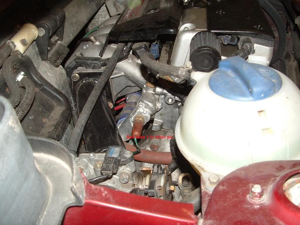
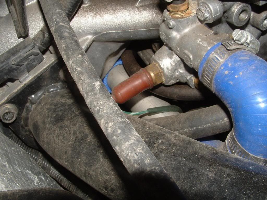
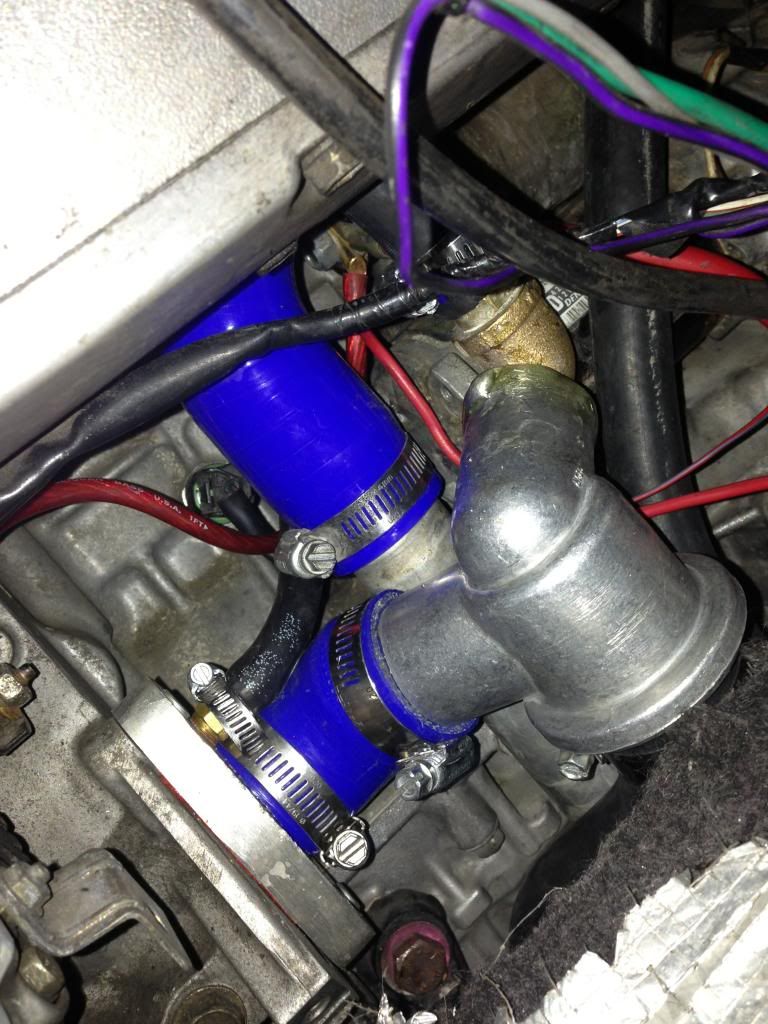
having redone all the original MWB cooling system. I think I know the area you are talking about, and I ended up using two 90 degree pieces, they just barely fit. You are talking about this area here, where the fabbed 180 degree aluminum piece with the coolant temp sensor is, right?


What thermostat are you planning on using?

Pete

Exactly the spot Pete. Is that the final fabricated piece? I was considering using the stock outlet with the 180 and run an aluminum tube under the intake (like in your pic). I am heading over to my machine shop pal's place today to discuss fabb'ing the piece in your pic rather than use the 180 hose. Curious is how your outlet clears the lower bolt hole ok? Can't see from the angle.

I have a couple of thermostats - one from a Fiat 124 and another from a Lancia Beta. The Beta t stat I think is a better fit.
 
I think I confused myself and didn't read your post enough times Pete ;)

That pic is your OLD (MWB) setup? If so are you suggesting I stick with stock outlet and create the bends myself using 180 or 2 90 degree bends?

Thanks...
 
That's correct, it's my old system

And that fabbed piece is yours for the asking, I am not using it anymore. Not that there was really anything wrong with it. The inside diameter may have been a touch small, and I didn't think the water would flow very well around those sharp 90 degree bends.

The original fabricator (Jonathan) assured me the piece would flow fine, but I went through and changed everything to be sure.

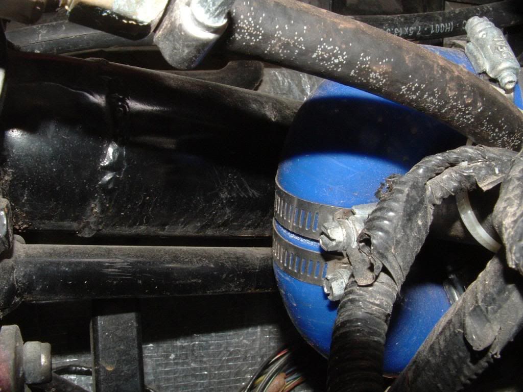
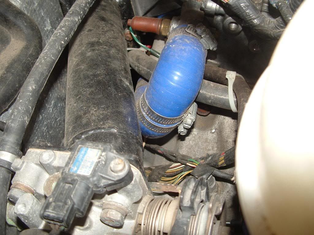
Here is the current arrangement, at least as well as I can shoot that very tight area of the engine compartment:


I went with a 185 degree beta thermostat, which is visible in this shot:


The fit in that area is even tighter. But I had to get rid of the old single-action system the car came with, it just flat did not work.

Pete
 
Thanks Pete!

I am glad to know I am going down the right path. And I appreciate the offer for the fabb'd piece but will let you keep it as your backup and go the same/similar route you ended up doing.

Getting close...!
-Tim
 
Can I ask how you are feeding your heater core?

I see a line in the t-stat pic that runs from the custom plate where the stock t-stat was. I assume that feeds one line. Where is the other one coming from?

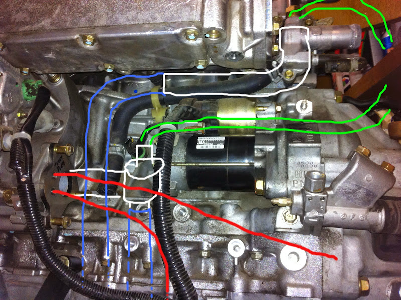
This was a pic I had sent to Matt based upon my own interpretation how the plumbing should go. I didn't take circulation into account but would figure that out later:

IMG_00057-1.jpg


From the WP, the white line(s) are the connection to the external thermostat. That thermostat will T into a soft line to the hard line under car to rad. Upper T will connect to bottom of overflow tank (yellow/green lines).

The red lines from the WP plate go to heater core and hard line under car.

The white lines from the head (pic upper right) are custom aluminum pipe that run to soft line that runs to hard lines under car to rad.

The last yellow/green line (from head), run to overflow tank - upper connector.

I know now just looking at my pic the heater core lines are wrong. I can't feed it back to the pump like that :( It needs to flow from the plumbing return from the head. Maybe intercepted in the aluminum tube that runs under the intake manifold? Crap - I thought I had this figured out... :(
 
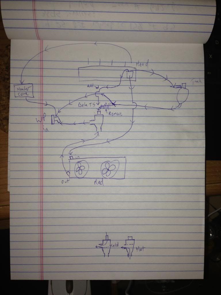
There are 4 different distinct circuits that have to be handled

1. Main (radiator) circuit
2. Bypass (warmup) circuit)
3. Heater core circuit
4. The overflow tank circuit

The heater core circuit starts at the back of the block (back as in, facing the rear bumper) near the transmission. From there it feeds the heater core, and then the return path is plumbed into a reducer that makes the line more like a 3/8 or 1/4 rather than the usual 5/8 heater hose. From the reduced hose size, it goes into a banjo bolt that bolts to the bottom of the water pump inlet housing, underneath the fabbed aluminum manifold piece. That feeds it to the same place as the two hoses that plumb into the fabbed aluminum manifold piece.

I think I have a hand-drawn map of all 4 circuits around here somewhere, if that's not clear.

Pete
 
Pete,

The # of circuits makes sense but I am a little lost in your description in the last sentence. I think the issue I have is I have been following the MWB "flow" and it is not taking into account proper bypass for warmup which you are taking care...other words, if you find that drawing please post it :)

Thanks...!
 
perfect sense...

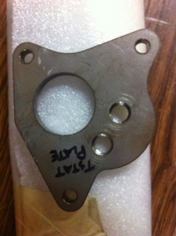
Thanks Pete. This explains the design that Jonathan put into this plate he did for Matt I got.

IMG_00074.jpg


instead of the banjo fix you used.
 
Nice. I waited as long as I could

but summer was full on so I had to forge ahead with creating my own.

It looks like you will still have to neck the heater hose down to a much smaller diameter to feed it into one of the two smaller holes. Surprisingly, this does not seem to affect the cabin heating function very much. At least not here in Texas... :)

What's the plan to plumb lines into those holes in that piece? NPT tap them for a nipple?

Pete
 
Back
Top