Working on the House....

Screenshot_20240501-200334.png

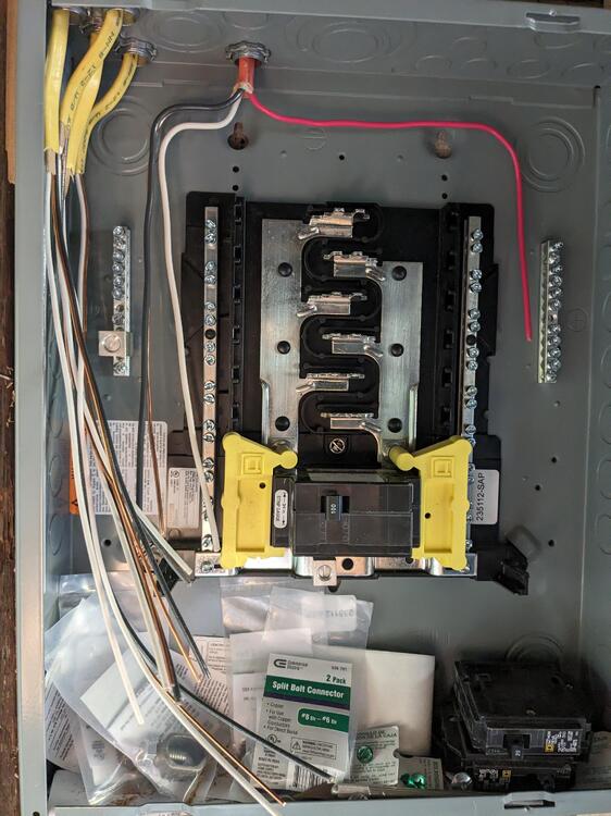
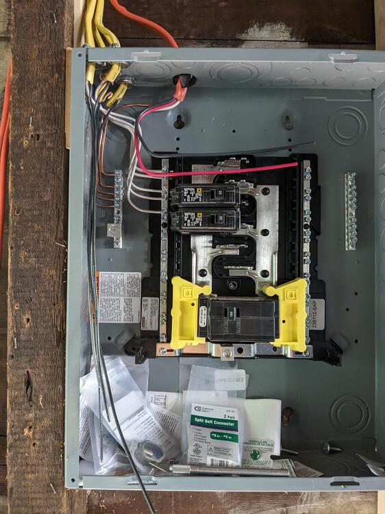
The sub panel is a 12 circuit, and I added the mains breaker to kill the entire garage.
PXL_20240501_225714295.jpg
I wonder if I still need an external junction with something like the split bolts to connect the buried line to the line that would then pass inside & connect to the breaker?

PXL_20240501_191700889.jpg

Since it is a sub panel, the ground requirements may be less than the 2 8' rods? It's still a separate structure, which is why I assumed the 2 grounding rods

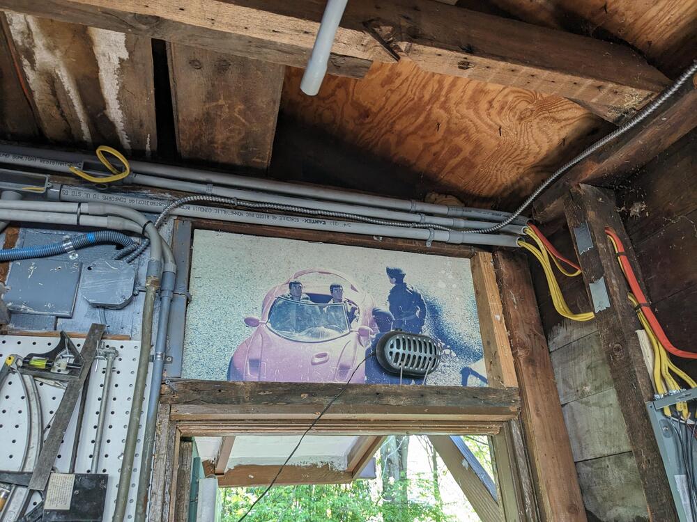
Running the 10/3 and 12/2 cables
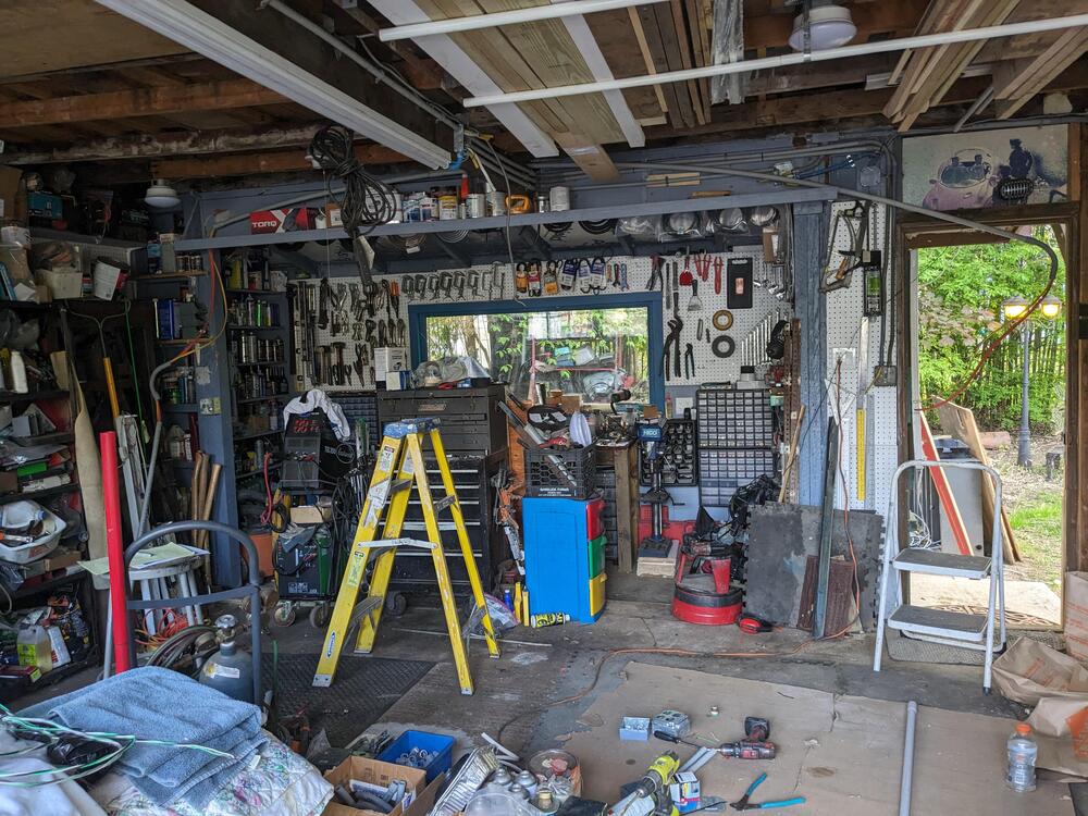
PXL_20240501_211831965.jpg
For those circuits, what I'm intending are joined boxes , with one carrying the 10/3, and the upper the 12/2 and 120v receptacles. I would only have 3 240v in total on the side, the 120v I would add more.

Vertical placement on the post here, horizontal when it runs along the south wall at approx 4' off the floor

EDIT - ordered 10AWG solid copper THHN in red, black & white to run in the 3/4" conduit with the 12/2
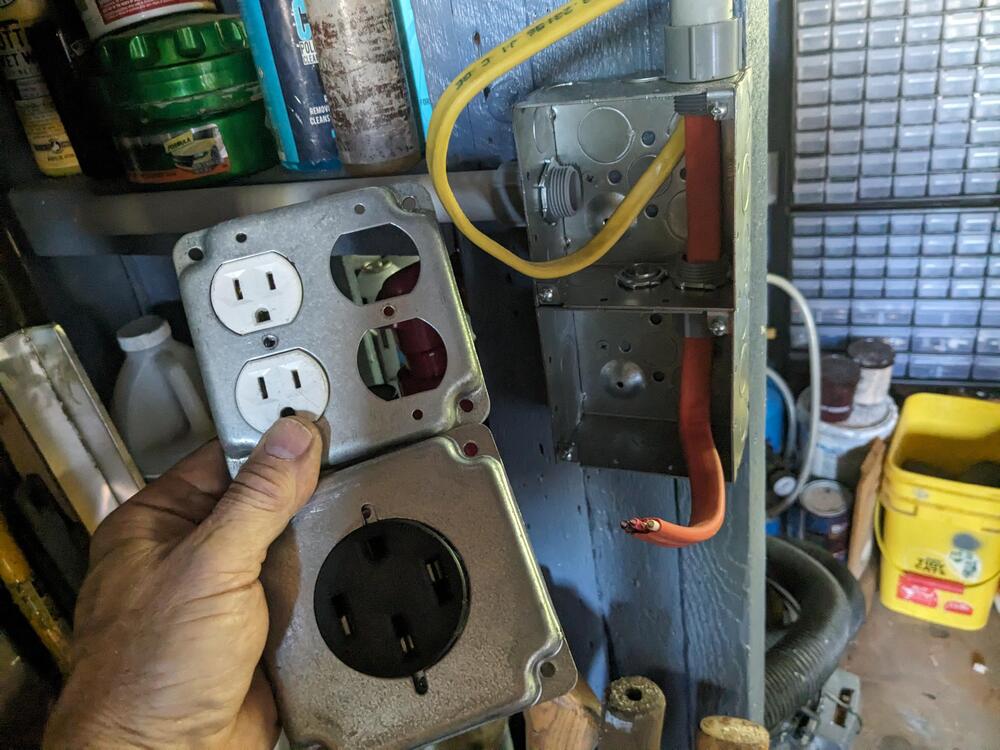
PXL_20240501_222139904.jpg
 
Last edited:
A sub panel no longer has separate grounds nearby by the latest versions of the NEC. You have to run a ground wire back to the main panel so all ground goes back to the main panel’s ground.

EDIT No grounding rods for the garage. EDIT This is incorrect. Ground rods and a grounding system is required in a separate structure.

Screenshot_20240501-200334.png

The sub panel is a 12 circuit, and I added the mains breaker to kill the entire garage.

PXL_20240501_225714295.jpg
I wonder if I still need an external junction with something like the split bolts to connect the buried line to the line that would then pass inside & connect to the breaker?

PXL_20240501_223941016.jpg
Since it is a sub panel, the ground requirements may be less than the 2 8' rods? It's still a separate structure, which is why I assumed the 2 grounding rods

Running the 10/3 and 12/2 cables

PXL_20240501_211831965.jpg
For those circuits, what I'm intending are joined boxes , with one carrying the 10/3, and the upper the 12/2 and 120v receptacles. I would only have 3 240v in total on the side, the 120v I would add more.

Vertical placement on the post here, horizontal when it runs along the south wall at approx 4' off the floor
PXL_20240501_222139904.jpg
 
Last edited:
A sub panel no longer has separate grounds nearby by the latest versions of the NEC. You have to run a ground wire back to the main panel so all ground goes back to the main panel’s ground.

No grounding rods for the garage.
Thank you Karl.

I'm was confused about that, as this one example had indicated otherwise (link) - note it is from 2022 :

screenshot-crossfieldgroup.com-2024.05.02-07_09_26.png


The question would then be what AWG the grounding wire needs to be. I will have to up-size the conduit for the buried feed to allow for that inclusion.
 
Thank you Karl.

I'm was confused about that, as this one example had indicated otherwise (link) - note it is from 2022 :

View attachment 84265

The question would then be what AWG the grounding wire needs to be. I will have to up-size the conduit for the buried feed to allow for that inclusion.
Edited

The #8 copper in the direct burial wire you show in your previous post is sufficient for the amperage you are running.

I added a sub box for the far end of our house as our main box was maxed out. I had repurposed a pair of circuits in the main box which had served an electric cooktop which had no ground wire (old codes). I added the ground wire back to the box as a separate wire. The neutral and grounds are isolated from each other in this box.
 
Last edited:
Thank you Karl.

I'm was confused about that, as this one example had indicated otherwise (link) - note it is from 2022 :

View attachment 84265

The question would then be what AWG the grounding wire needs to be. I will have to up-size the conduit for the buried feed to allow for that inclusion.
I need to do a bit more research, this is one of the more complex bits of the more recent NEC codes.

EDITED

You do need both. The neutral and ground cannot be bonded (connected to each other within the box) so ensure all neutrals go to the neutral bar and all grounds will go to a separate ground bar. There is a difference between sub panels within one structure and a sub panel in a separate structure.

The ground rods should be as far part as possible and bury the bare uninsulated ground wire running between them to maximize the grounding. At my house this is extremely easy as I live on a sand bank and can push a 10’ ground rod in with just hand pressure. My old house with clay soil it took me half an hour to pound an 8’ one into the ground…
 
Last edited:
I need to do a bit more research, this is one of the more complex bits of the more recent NEC codes.

EDITED

You do need both. The neutral and ground cannot be bonded (connected to each other within the box) so ensure all neutrals go to the neutral bar and all grounds will go to a separate ground bar. There is a difference between sub panels within one structure and a sub panel in a separate structure.

The ground rods should be as far part as possible and bury the bare uninsulated ground wire running between them to maximize the grounding. At my house this is extremely easy as I live on a sand bank and can push a 10’ ground rod in with just hand pressure. My old house with clay soil it took me half an hour to pound an 8’ one into the ground…
@lookforjoe I presume you have a breaker in the main house box for this sub box?

OK. I have planned on keeping all neutrals on the neutral & separate from the earth/ground bar(s).

I already bought the 8' rods, so I'll plan on using them. My soil goes to clay at only a few feet under, so I'm expecting it to be a bitch. I didn't know whether connecting ground wire between rods was to be buried, so thanks for clarification on that.

There is currently a breaker that only serves the 120v supply to the garage. I need to add a circuit breaker for the new circuit (when I get to that point)

In the new box you remove the ‘green’ screw from the neutral connector so the neutral isn’t grounded/bonded to the box.

This has been a fussy part of the code for a long while. One of the issues in the past has been if there is a water line or rigid metallic conduit between the two buildings there can be issues in terms of the bonding of the two. Due to corrosion the ground can be lost between the buildings which could create an overheating condition on the neutral if everything went south.

Electricity, unlike many of the dangerous things we flirt with where we have to work at doing something to be killed or injured by it, is just one small mistake away from taking us out.
 
OK. I have planned on keeping all neutrals on the neutral & separate from the earth/ground bar(s).

I already bought the 8' rods, so I'll plan on using them. My soil goes to clay at only a few feet under, so I'm expecting it to be a bitch. I didn't know whether connecting ground wire between rods was to be buried, so thanks for clarification on that.

There is currently a breaker that only serves the 120v supply to the garage. I need to add a circuit breaker for the new circuit (when I get to that point)
I ran one continuous wire from the box to the first grounding rod, attached it to that rod, and then ran the same wire to the other rod @30’ away. This ensures that as long as the wire is attached at the box it has continuity to at least one rod without worrying about corrosion or a loose fastener on one rod or the other.

I also put them all the way into the ground with a short length of 2” pvc pipe and a cap over it to give some protection and ease finding the thing for future inspection.
 
Had an hour after work before Pilates class with the Mrs, so I started tidying up the branches at the panel & end wall, and began wiring the branch grounds and then the neutrals to the sub panel

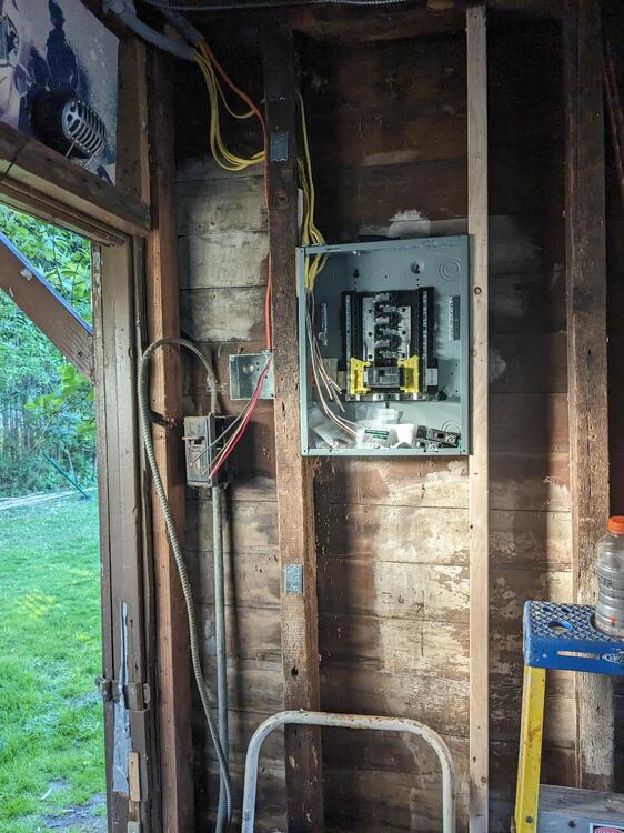
Edit - found a note in another relayed article that said sub panel must be at least 6'6" from the ground to the top surface. I didn't know that, I just placed mine up relatively high as that's what I've seen. I measured mine & it's exactly 6'6" from the floor to the top edge, whew!

PXL_20240502_200430711.jpg

PXL_20240502_200435307.jpg
 
Last edited:
  • Like
Reactions: 86X
Had an hour after work before Pilates class with the Mrs, so I started tidying up the branches at the panel & end wall, and began wiring the branch grounds and then the neutrals to the sub panel

Edit - found a note in another relayed article that said sub panel must be at least 6'6" from the ground to the top surface. I didn't know that, I just placed mine up relatively high as that's what I've seen. I measured mine & it's exactly 6'6" from the floor to the top edge, whew!

PXL_20240502_200430711.jpg

PXL_20240502_200435307.jpg
I believe that is to reach the main breaker, not the box itself
 
OK - in that case I'm all good. Don't want to raise the panel.
The height of the main breaker is so most any adult can reach it to shut off the main power. It is a maximum.

NEC states that circuit breakers shall be installed so that the center of the grip of the operating handle of the circuit breaker, when in its highest position, will not be more than 6 ft. 7 in. above the floor or working platform. NEC380-8a.
 
For the time being, I added a junction box to replace the old single fuse sub panel, and added 12AWG from there to the new sub panel, to one of the phases. I understand doing this is not to any code. I only have the few circuits running off it, until I get the 6AWG underground feed in place, then I'll properly wire the sub panel with the two phases and connect the 240 branch.

Added a ground from the panel to the conduit used to supply the 120v supply

PXL_20240506_200758753.jpg


Wiring to the 240 outlet above, waiting for the 10AWG individual wires, then I'll wire the receptacle
PXL_20240505_171926341.jpg


added a GFCI receptacle & a regular on the load side, by the door, separate fused branch from the branches in the west addition and what will be on the south wall. I will continue that branch into the north wall when that addition happens
PXL_20240506_202541924.jpg


All the conduit tidied up on this side now
PXL_20240506_210025613.jpg
 
Back
Top